Carbon fiber weave describes how warp and weft tows interlace in a fabric. The interlacing pattern controls stability, tow movement, and visible surface texture.
In CFRP laminates, the weave is only part of the structure. Resin selection, ply orientation, compaction, and cure control also determine final performance.
How Weave Type Affects Strength Stiffness Appearance and Processing
Weave type changes fiber crimp, which is tow bending inside the fabric. Higher crimp can reduce straight fiber efficiency under tensile loading.
Weave type affects several CFRP design and processing factors:
- Fiber crimp and tensile efficiency
- Drapability over curved tools
- Surface appearance and visible pattern
- Resin flow and wet-out behavior
- Cutting quality and edge stability
- Risk of waviness, dry spots, and distorted fiber angles
Open or flexible weaves drape better over curved tools. Stable weaves cut cleanly but may resist forming around tight contours.
The selected pattern also affects resin flow, surface print, and trimming quality. Poor control can cause waviness, dry spots, or distorted fiber angles.
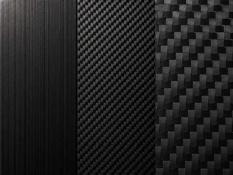
Common Carbon Fiber Weave Types
Common carbon fiber weave types differ in interlacing, crimp, drape, surface appearance, and laminate design use.
| Weave Type | Main Feature | Best For | Main Limitation |
|---|---|---|---|
| Plain weave | Tight 1×1 interlacing | Flat panels and stable cutting | Lower drape on curved molds |
| Twill weave | Diagonal 2×2 or 4×4 pattern | Curved parts and visible surfaces | Can skew during layup |
| Satin weave | Longer tow floats | Complex contours | More sensitive to distortion |
| Spread tow fabric | Flattened low-crimp bands | Lightweight smooth panels | Gaps and overlaps are visible |
| Unidirectional fiber | Fibers mainly in one direction | Directional stiffness | Not a woven fabric |
Plain Weave Carbon Fiber with 1×1 Over Under Interlacing
Plain weave uses the tightest common interlacing pattern, with each tow frequently crossing adjacent tows. This creates high fabric stability during cutting and handling.
The same interlacing increases crimp compared with more open fabrics. That crimp can slightly reduce fiber efficiency in highly loaded directions.
Plain weave is useful for flat panels, small parts, and edge-sensitive layups. Excessive forming force can create wrinkles on curved molds.
Twill Weave Carbon Fiber with 2×2 and 4×4 Diagonal Patterns
Twill weave forms a diagonal surface pattern by shifting tow crossovers across the fabric. This reduces crimp and improves drapability compared with plain weave.
The diagonal architecture conforms well to compound curves when handled correctly. However, the pattern can skew if tension is uneven during layup.
Twill is often selected for visible carbon fiber parts. Operators must align the diagonal consistently to avoid cosmetic mismatch between plies.
Satin Weave Carbon Fiber with 4HS 5HS and 8HS Patterns
Satin weave places longer tow floats across the fabric surface. These longer floats reduce interlacing and allow high formability over complex surfaces.
Lower interlacing can improve fiber straightness in selected directions. It can also make the fabric more prone to snagging or local distortion.
Satin fabrics need careful ply support during cutting and transfer. Controlled tension prevents tow separation and pattern shift before consolidation.
Spread Tow Carbon Fiber Fabric with Low Crimp Tapes
Spread tow fabric uses flattened tows that create broad, thin fiber bands. The architecture lowers crimp and helps produce smooth laminate surfaces.
Because the tows are wider, gaps and overlaps become more visible. Cutting, nesting, and ply placement must control band alignment carefully.
Spread tow is valuable for lightweight panels and cosmetic skins. It also supports thin laminate build-up with reduced print-through risk.
Unidirectional Carbon Fiber as a Non Woven Fiber Architecture
Unidirectional carbon fiber places most fibers in a single load direction. It is not a woven pattern, but it is central to laminate design.
UD plies provide efficient stiffness where loads are predictable. They need cross plies or woven skins to improve handling and damage tolerance.
Plain Weave vs Twill Weave vs Satin Weave Carbon Fiber
These weave families are compared by stability, crimp, drape, appearance, and handling behavior.
Weave Stability and Fiber Crimp
Plain weave has high interlacing density, so it resists fraying and tow shift. The tradeoff is increased crimp and reduced fiber straightness.
Twill lowers crossover frequency and improves load transfer along tow paths. Satin lowers interlacing further, but needs stricter handling control.
Designers should match crimp level with the expected load direction. Straight fibers carry tensile loads more efficiently than heavily undulated fibers.
Drapability and Forming Over Curved Surfaces
Drapability measures how fabric conforms without wrinkling, bridging, or tow distortion. Twill and satin usually form more easily than plain weave.
During layup, operators control drape by balancing tension and local smoothing. Excess pulling can rotate the weave and change fiber orientation.
On deep or double-curved tools, ply darts may be needed. Any cut relief must avoid severing critical load paths.
Surface Appearance and Visible Carbon Fiber Patterns
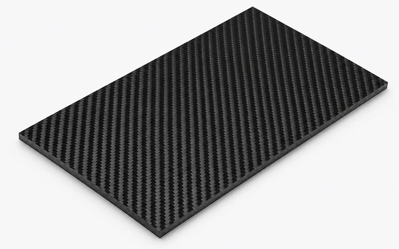
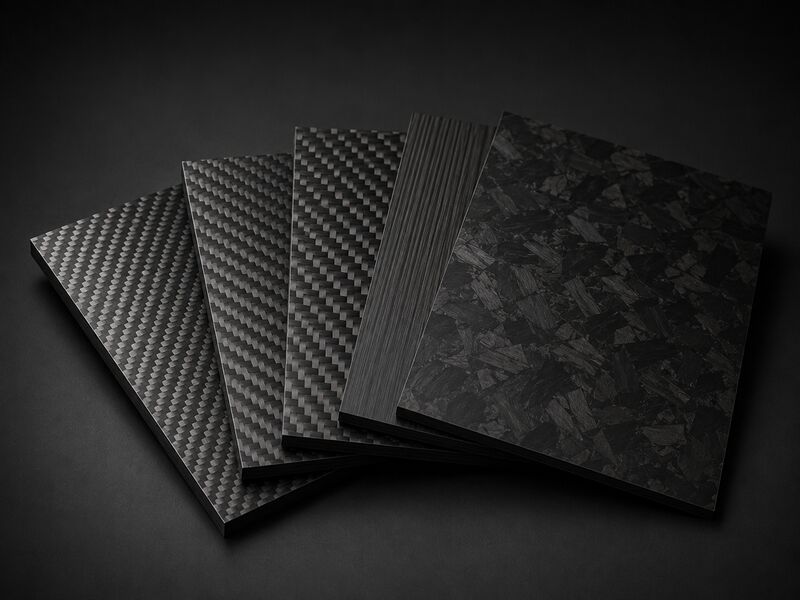
Plain weave gives a small checker pattern with uniform visual texture. Twill shows a diagonal pattern often used on exposed CFRP surfaces.
Satin creates longer reflective bands and a smoother visual flow. Spread tow provides a flatter technical appearance with less surface texture.
Cosmetic consistency depends on the selected carbon fiber pattern, ply orientation, resin wet-out, and tool finish. Misaligned fabric creates visible pattern drift after curing.
Cutting Handling and Edge Stability
Plain weave handles well because frequent interlacing locks the tow network. Twill and satin need more support during cutting and transfer.
Sharp blades, controlled backing, and clean ply lifting reduce frayed edges. Poor handling can pull tows and create local fiber waviness.
For prepreg, tack can improve placement but may hide skew. Dry fabrics require careful nesting and low-disturbance movement.
Tow Size and Fabric Weight in Carbon Fiber Weave Selection
Tow size and fabric weight affect appearance, ply thickness, drape, resin demand, and laminate build-up.
1K 3K 6K 12K and 24K Tow Size Effects
Smaller tow sizes create finer weave patterns and smoother cosmetic detail. Larger tow sizes produce bolder patterns and faster laminate build-up.
| Tow Size | Appearance | Processing Effect | Common Selection Logic |
|---|---|---|---|
| 1K | Very fine weave detail | Good for small features | Used when cosmetic detail is critical |
| 3K | Fine and common carbon look | Balanced handling and appearance | Used for visible CFRP sheets and panels |
| 6K | Medium weave scale | Faster build-up than 3K | Used when surface and thickness both matter |
| 12K | Bold weave pattern | Builds thickness faster | Used for larger parts and cost control |
| 24K | Large visible bundles | Less suitable for tight radii | Used when fast build-up is more important |
Use the chosen tow size to balance surface appearance, forming response, and material cost. Larger bundles may resist tight curvature and show stronger print-through.
The tow choice also affects resin wet-out and void sensitivity. Dense tow bundles need controlled consolidation to avoid trapped air.
Carbon Fiber Weave Types in Laminate Design
Weave selection must support ply orientation, load transfer, stability, resin control, and thickness targets.
Fiber Orientation Ply Schedule and Load Path Alignment
Laminate design starts by aligning fibers with major load paths. Woven fabrics provide fiber directions within each ply, but not equal performance everywhere.
Ply schedules combine woven plies, UD layers, and local reinforcements. This controls stiffness, bending response, and damage growth.
If the weave angle shifts during layup, design assumptions become less reliable. Templates, ply marks, and tool references help maintain orientation.
Balanced and Symmetric Stacking for Dimensional Stability
Balanced stacking reduces twisting caused by unequal fiber directions. Symmetric stacking reduces warpage after cure and cooling.
Woven plies help balance in-plane properties when oriented correctly. They still require mirrored placement around the laminate mid-plane.
Unbalanced layups can distort thin panels or bonded assemblies. Dimensional inspection should verify flatness before secondary machining.
Resin Content Void Content and Laminate Thickness Control
Resin content controls weight, surface wet-out, and fiber support. Too much resin creates heavy, resin-rich zones with lower fiber efficiency.
Too little resin can leave dry fibers and weak bonding between tows. Compaction, debulking, and controlled bleed paths manage resin distribution.
Void content must stay below the project specification to protect interlaminar strength and fatigue behavior. Thickness checks confirm consolidation consistency across the part.
Mechanical Performance by Carbon Fiber Weave Type
Mechanical behavior depends on crimp, fiber alignment, resin quality, ply schedule, and defect control.
Tensile Stiffness and Flexural Strength by Weave Crimp
Tensile stiffness improves when fibers remain straight along the load direction. Crimp makes fibers bend before fully carrying load.
Plain weave is stable but has more crimp than twill or satin. Twill and satin can support better fiber efficiency when orientation is controlled.
Flexural strength also depends on compression-side stability and resin support. Fiber waviness near the surface can reduce bending performance.
Compression Strength and Interlaminar Shear Behavior
Compression strength is sensitive to fiber waviness and tow undulation. A distorted weave can trigger local buckling under compressive load.
Interlaminar shear depends on resin quality and bonding between plies. Voids, dry spots, and contamination reduce load transfer through thickness.
Compaction and cure control support stable tow geometry. The selected weave should match the expected compression and shear environment.
Fatigue Resistance Under Repeated Loading
Fatigue resistance depends on fiber alignment, resin toughness, and defect levels. Repeated loading can grow matrix cracks around tow crossovers.
Lower-crimp fabrics may reduce stress concentrations in aligned load paths. However, poor consolidation can erase this benefit.
Coupon testing should represent the actual weave, stacking sequence, and process route. Testing unrelated fabric forms gives weak design confidence.
Impact Resistance and Damage Tolerance by Fabric Architecture
Woven fabrics can spread impact energy across interlaced tow networks. This may improve visible damage tolerance compared with brittle local architectures.
Plain weave offers stable tow restraint, while satin offers better formability. Spread tow can reduce weight but may show larger local damage zones.
Damage tolerance also depends on resin toughness and ply interfaces. Inspection after impact should check delamination, not only surface marks.
Thermal Expansion Electrical Conductivity and Galvanic Corrosion Risk
Carbon fiber has directional thermal and electrical behavior. Weave orientation controls how these properties distribute through a laminate.
Conductive carbon fibers can create galvanic corrosion when contacting certain metals. Isolation layers, coatings, and sealed joints reduce this risk.
Thermal expansion mismatch can also stress bonded joints. Balanced weave orientation helps reduce distortion during temperature changes.
Manufacturing Considerations for Carbon Fiber Weave Patterns
Manufacturing success depends on fabric form, ply control, consolidation, cure method, and distortion prevention.
Dry Woven Fabric Prepreg and Unidirectional Tape Formats
Dry woven fabric is used for infusion, RTM, and some compression routes. It needs careful handling because loose tows can shift easily.
Prepreg combines carbon fabric with controlled resin and tack. It improves placement control but requires storage, thawing, and cure discipline.
UD tape supports directional reinforcement and automated placement options. It must be combined with cross reinforcement for multidirectional loads.
Ply Cutting Nesting and Weave Orientation Control
Ply cutting should preserve tow alignment and minimize frayed edges. Cutting tables, backing films, and sharp tools reduce fabric disturbance.
Key controls before layup include:
- Keep the approved weave direction during nesting
- Use sharp blades to reduce frayed edges
- Add backing films when the fabric is easy to distort
- Mark each ply orientation before transfer
- Avoid unauthorized ply rotation
- Place fabric against tool datums consistently
Nesting must account for weave direction and cosmetic pattern flow. Rotating plies without approval can change stiffness and appearance.
Each ply should carry orientation marks before transfer. These references help operators place fabric against tool datums consistently.
Layup Vacuum Bagging and Autoclave Curing
Layup begins with clean tools, release control, and planned ply sequence. Each ply is placed without dragging across the previous layer.
Vacuum bagging removes air and applies compaction before curing. Leaks can cause porosity, resin movement, and weak laminate zones.
Autoclave curing adds controlled pressure and temperature for prepreg laminates. The selected cure range must suit the resin system and tooling.
Resin Infusion RTM and Compression Molding with Drape Control
Infusion and RTM require predictable permeability through the woven preform. Tight weaves may slow resin flow and increase dry spot risk.
Drape control is critical before resin introduction. A distorted dry preform will lock the wrong fiber angles into the cured part.
Compression molding can form complex parts quickly when charge placement is controlled. Excess material flow can shear the weave and create resin-rich zones.
Roll Wrapping Tubular Layup and Woven Tube Appearance Control
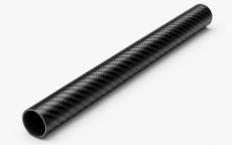
Roll wrapping uses fabric or prepreg around a mandrel. The weave angle affects torsional stiffness and surface pattern alignment.
Tubular layup needs consistent overlap control to avoid ridges. Poor overlap placement creates local thickness changes and machining problems.
For visible carbon fiber tubes, seam location and pattern continuity matter.. Controlled wrapping tension prevents diagonal drift around the circumference.
Defects and Inspection in Woven Carbon Fiber Laminates
Woven CFRP defects often begin with fabric distortion, poor wet-out, trapped air, or machining damage.
| Defect | Main Cause | Effect | Inspection Method |
|---|---|---|---|
| Fiber waviness | Tow deviation or poor drape | Lower stiffness and compression risk | Visual inspection |
| Tow skew | Uneven tension or aggressive smoothing | Changed fiber angle | Ply orientation check |
| Porosity | Trapped air or poor consolidation | Lower interlaminar strength | Ultrasonic C scan |
| Dry spots | Poor resin flow | Weak bonding | Visual or section check |
| Delamination | Machining damage or weak interfaces | Internal structural damage | Tap test or C scan |
| Frayed edges | Poor cutting support or worn tools | Edge weakness and fiber pull-out | Visual inspection |
Fiber Waviness Tow Skew and Weave Angle Distortion
Fiber waviness occurs when tows deviate from their intended path. It reduces stiffness and can trigger compression failure.
Tow skew often develops during draping, transfer, or aggressive smoothing. Operators should use controlled tension and avoid dragging fabric.
Weave angle distortion changes laminate anisotropy and cosmetic alignment. Visual checks before cure prevent permanent geometry errors.
Porosity Dry Spots Resin Rich Areas and Void Content
Porosity forms when air remains trapped during consolidation or infusion. It weakens interlaminar properties and can reduce fatigue life.
Dry spots occur when resin fails to wet the fiber network. Resin-rich areas add weight and create brittle matrix zones.
Flow media, vents, debulking, and pressure control reduce these defects. Inspection should compare critical areas with process records.
Delamination Frayed Tows and Edge Breakout During Machining
Delamination during machining begins when cutting forces lift weak ply interfaces. Woven fabrics can fray if tools pull unsupported tows.
When cutting carbon fiber, sharp cutters, backing support, and the correct feed strategy help reduce edge breakout and fiber pull-out. Worn tools can increase heat and machining damage.
Edge sealing may be needed for exposed carbon fiber parts. It protects fibers from moisture paths and handling damage.
Visual Inspection Ultrasonic C Scan and Coupon Testing
Inspection should match the part risk, laminate thickness, and service load. Cosmetic acceptance alone is not enough for structural carbon fiber parts.
Common inspection methods include:
- Visual inspection for weave distortion, surface print, dry zones, and edge defects
- Tap testing for suspected delamination in accessible areas
- Ultrasonic C scan for internal discontinuities in CFRP components
- Coupon testing for strength, stiffness, and process repeatability
- Process record review for cure cycle, pressure, and resin flow control
Visual inspection cannot reliably detect hidden delamination inside thick laminates. Ultrasonic C scan and coupon testing provide stronger evidence for structural quality.
FAQ
Which Carbon Fiber Weave Type is Strongest?
No weave type is always strongest. Strength depends on fiber grade, crimp, orientation, resin quality, and defects.
UD plies often give the highest directional stiffness. Woven fabrics can improve handling, impact spread, and multidirectional balance.
What is the Difference Between 1×1 Plain Weave and 2×2 Twill Carbon Fiber?
Plain weave has frequent interlacing and high stability. Twill has a diagonal pattern with lower crimp and better drape.
Plain weave cuts cleanly for flat parts. Twill forms curved surfaces more easily and gives a different visible pattern.
When Should Spread Tow Carbon Fiber Be Used Instead of Standard Tow Fabric?
Use spread tow when a thin laminate and smooth surface are required. It also helps reduce crimp in lightweight panel designs.
It needs tighter placement control than standard tow fabrics. Gaps and overlaps are more visible in the cured surface.