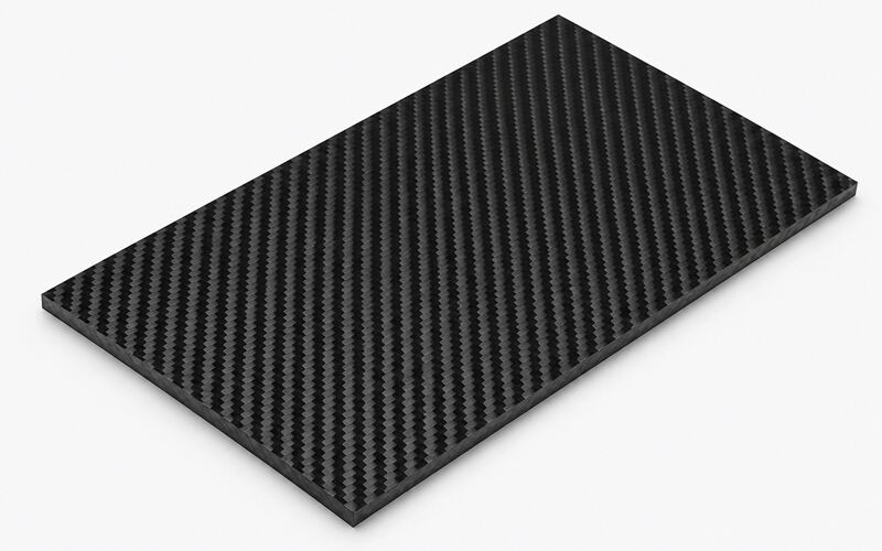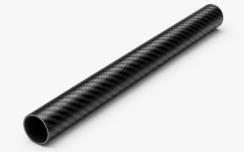
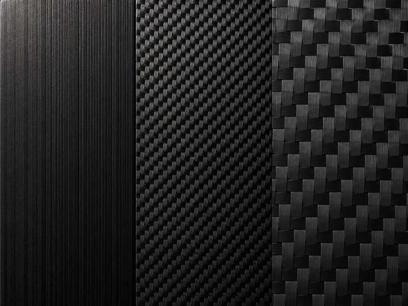
Carbon fiber reinforcement comes in distinct forms that shape how a laminate carries load.
Unidirectional fiber, often called UD, holds all filaments aligned in one direction within a single ply. A light cross thread or scrim keeps the tow spaced but adds no structural strength.
This arrangement places maximum fiber volume along one axis. Load capacity peaks in that direction, while the transverse direction depends almost entirely on resin.
Woven carbon fiber fabric interlaces tows in two directions, commonly at 0 and 90 degrees. Plain, twill, and satin weaves differ in how often fibers cross over one another.
This interlacing creates a self-supporting sheet that resists fraying during handling. The crossover points introduce fiber crimp, which changes stiffness compared with straight UD tow.
Unidirectional vs Woven Carbon Fiber
Structural behavior between UD and woven fabric differs mainly through fiber path, alignment, crimp, and handling stability.
| Factor | Unidirectional Carbon Fiber | Woven Carbon Fiber |
|---|---|---|
| Fiber alignment | Fibers run primarily in one direction | Fibers interlace in two principal directions |
| Load distribution | Concentrates strength and stiffness along one axis | Distributes load more evenly across two axes |
| Fiber crimp | Minimal because fibers remain relatively straight | Present where tows pass over and under each other |
| Directional behavior | Highly anisotropic | More balanced within the fabric plane |
| Handling stability | More likely to shift, split, or fray | Interlaced tows hold the fabric together |
| Drapability | Less adaptable to compound curves | Better suited to curved and complex surfaces |
| Surface appearance | Linear and relatively uniform | Visible plain, twill, or satin weave pattern |
| Typical use | Beams, spars, tubes, and directional reinforcement | Panels, shells, joints, and cosmetic surfaces |
Fiber Alignment and Load Paths
UD tow runs straight, so applied load travels directly along the fiber axis.
Woven fiber divides reinforcement between two directions, reducing peak stiffness in either single direction.
Fiber Crimp and Straightness
Crimp forms where woven tows bend over and under adjacent fibers. This waviness lowers modulus and creates local stress concentrations that are largely absent in straight UD reinforcement.
Directional and Balanced Properties
UD plies produce strongly directional, anisotropic properties suited to predictable load cases.
Woven fabric delivers more balanced in-plane properties across its two main fiber directions.
Handling and Fabric Stability
Woven fabric resists distortion during cutting and layup because interlaced tows lock one another in place. UD plies shift and fray more easily, requiring careful handling and backing-film support.
Mechanical Performance Comparison
Mechanical response depends heavily on fiber straightness, orientation, laminate support, and how load enters the structure.
Tensile Strength and Stiffness
Straight UD fiber achieves higher tensile strength and modulus along its primary axis than woven fabric with equivalent fiber content. Crimp in woven tow reduces achievable stiffness by introducing bending stress under axial load.
A carbon fiber part loaded mainly in one direction benefits from UD reinforcement.
Woven fabric suits parts loaded along two axes without a single dominant direction.
Compression and Buckling Behavior
UD laminates can show earlier fiber microbuckling under compression if ply support is insufficient. Woven fabric often resists localized buckling more effectively because interlacing restrains individual tow movement.
Off-Axis and Shear Performance
Woven fabric provides more consistent shear performance across several loading angles. UD plies require angled stacking, such as positive and negative 45-degree orientations, to achieve comparable off-axis strength.
Impact and Damage Tolerance
The interlaced woven structure distributes impact energy across crossing tows, limiting localized fiber breakage.
UD plies can split along the fiber direction, allowing damage to propagate farther before visible failure.
Crack Growth and Failure Modes
Cracks in UD laminates tend to run parallel to the fiber direction, producing longitudinal splitting.
Woven laminates often show more distributed microcracking because interlacing interrupts the crack path.
Layup Design and Fiber Orientation
Orientation choices determine how a carbon fiber laminate responds to bending, tension, shear, torsion, and combined loading.
- 0-degree plies: Align fibers with the primary load path to maximize longitudinal strength and stiffness.
- 90-degree plies: Add transverse support, improve width-wise strength, and reduce longitudinal splitting.
- +45-degree plies: Carry diagonal shear loads and contribute to torsional resistance.
- -45-degree plies: Balance positive-angle reinforcement and reduce directional twisting behavior.
- Quasi-isotropic stacks: Combine several orientations to create more uniform in-plane properties.
- Localized UD plies: Reinforce high-load zones without adding equal thickness across the entire part.
- Woven surface plies: Improve handling, impact distribution, and visible surface appearance.
0- and 90-Degree Layups
Zero-degree plies align fibers with the main load path, maximizing stiffness in that direction. Ninety-degree plies add transverse support, control width-wise strength, and reduce splitting.
Plus- and Minus-45-Degree Layups
Angled plies at positive and negative 45 degrees improve shear and torsional performance. Designers often pair UD plies at these angles to reproduce the balanced behavior of woven reinforcement.
Quasi-Isotropic Laminate Design
A quasi-isotropic stack combines several orientations so in-plane properties become nearly uniform. This approach reduces directional weakness but can increase ply count, layup labor, and laminate thickness.
Ply Ratios and Stacking Sequences
Ply ratio defines how much reinforcement runs in each orientation relative to total laminate thickness. Stacking sequence controls bending stiffness, symmetry, coupling behavior, and resistance to warping after cure.
Localized and Hybrid Reinforcement
Local UD reinforcement strengthens specific load zones without adding unnecessary weight elsewhere. Combining UD strips with woven fabric creates hybrid laminates tuned to mixed loading conditions.
Drapability and Complex Shapes
Part geometry strongly influences whether woven fabric or UD reinforcement performs better during layup.
Woven Fabric Over Curved Molds
Woven fabric drapes more easily over curved and compound surfaces because interlacing allows in-plane shear deformation. This flexibility reduces wrinkling on complex carbon fiber molds.
UD Ply Gaps and Overlaps
UD plies resist shear deformation, so tight curves can create gaps or overlapping fibers. These defects form resin-rich zones and inconsistent laminate thickness after cure.
Fiber Distortion Around Corners
Sharp corners can force fiber waviness in both UD and woven plies. Excessive distortion lowers local stiffness and increases the risk of premature failure under load.
Manufacturing Considerations
Processing method influences fiber alignment control, resin distribution, labor requirements, and final laminate consistency.
Prepreg Layup and Ply Placement
Carbon fiber prepreg holds fiber and partially cured resin in a stable sheet, simplifying ply placement. Automated tape layup commonly uses UD prepreg to place precise and repeatable fiber angles.
Wet Layup and Infusion Processing
Woven fabric works well in wet layup and resin infusion because interlacing helps maintain fiber spacing during resin flow. UD reinforcement requires careful resin distribution to prevent dry zones along densely packed tows.
Resin Content and Fiber Volume
Resin content near 35% by weight is common for many structural laminates, directly affecting weight, stiffness, and consolidation. A higher fiber volume fraction can raise strength but also increases sensitivity to voids, dry areas, and misalignment.
Cutting and Material Handling
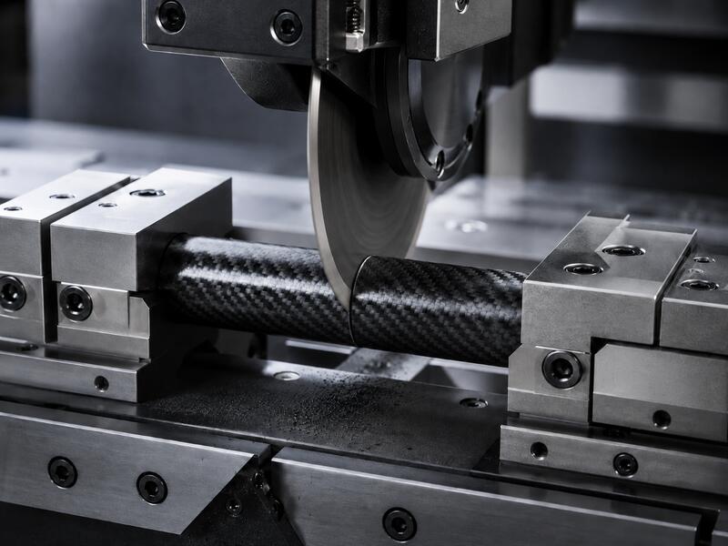
When cutting carbon fiber, woven fabric usually remains more stable along established patterns, while UD reinforcement often requires supportive backing and controlled cutting methods to prevent fiber slippage before layup.
Layup Defects and Quality Control
Fiber waviness, gaps, overlaps, and resin-rich pockets are common layup defects in both reinforcement forms. Visual inspection and ultrasonic scanning can verify alignment and detect voids before final assembly.
Surface Appearance and Finish
Surface texture reflects the underlying fiber architecture and affects cosmetic expectations for visible carbon fiber parts.
Visible Weave Patterns
Woven fabric produces recognizable visible weave patterns valued in cosmetic carbon fiber applications. Plain and twill weave create different surface textures beneath clear resin, while satin weave provides another variation in crossover structure and appearance.
UD Surface Appearance
UD plies show a smoother, linear surface with subtle fiber striping. This appearance suits structural parts where a decorative woven pattern is not required.
Print-Through and Cosmetic Defects
Print-through occurs when the underlying reinforcement texture becomes visible through the surface resin layer. Controlled resin content, surface films, sanding, and finishing can reduce print-through in both UD and woven laminates.
Cost Comparison
Cost differences result from material processing, layup labor, manufacturing yield, and inspection requirements rather than raw material price alone.
| Cost Factor | Unidirectional Carbon Fiber | Woven Carbon Fiber |
|---|---|---|
| Raw material processing | Often avoids the additional weaving stage | Includes weaving operations that raise material cost |
| Layup labor | Requires precise orientation and greater handling control | Stable sheets can reduce manual placement time |
| Equipment needs | May benefit from automated tape-laying equipment | Can be cut and placed using conventional layup methods |
| Material waste | Gaps, overlaps, and angle cutting can increase waste | Often offers better nesting on curved components |
| Inspection | Fiber-angle errors may require detailed verification | Weave distortion is often easier to identify visually |
| Rework risk | Misalignment can cause substantial performance loss | Interlaced construction reduces tow movement during layup |
| Total part cost | Can be lower for simple directional structures | Can be lower for complex shapes and manual production |
Material Cost
Woven fabric typically costs more per kilogram because weaving adds processing steps. UD tape may cost less in raw form but can require additional handling equipment and placement control.
Layup Labor
Woven fabric can accelerate layup because sheets remain stable and drape predictably. UD layup demands precise angle control, often increasing labor time for multidirectional designs.
Material Waste and Production Yield
Complex curves can generate higher UD material waste through trimming, gaps, and overlaps. Woven fabric often provides better nesting efficiency on curved or irregular components.
Inspection and Rework Costs
Fiber misalignment in UD plies can result in costly rework or rejected parts. Woven fabric distortion is often easier to identify visually, which can simplify initial inspection.
Typical Applications
Different carbon fiber applications require different balances of directional strength, multi-axis reinforcement, drapability, and surface appearance.
Beams, Spars, and Structural Tubes
UD reinforcement dominates beams, spars, and carbon fiber tubes where the primary load runs along one axis. Straight fiber alignment maximizes bending stiffness and axial strength in these components.
Panels and Flat Laminates
Flat carbon fiber sheets often combine woven surface plies with UD internal layers. This arrangement balances cosmetic appearance, handling stability, and directional strength.
Joints and Curved Components
Woven fabric adapts more readily to curved joints, corners, and transition zones. Its drapability reduces gaps, overlaps, and wrinkling compared with less deformable UD plies.
Sporting and Automotive Parts
Bicycle frames, automotive panels, monocoques, and similar CFRP components frequently combine both reinforcement forms. Designers balance stiffness, impact resistance, weight, and appearance through hybrid layups.
Hybrid Composite Structures
Hybrid structures pair UD strength with woven stability to meet mixed loading and geometric demands. This combination can improve structural efficiency without relying entirely on one reinforcement form.
How to Choose Between UD and Woven Carbon Fiber
Selection depends on load direction, part geometry, surface requirements, manufacturing method, and production budget.
- Identify the main load direction. Choose UD reinforcement when tension or bending acts primarily along one predictable axis.
- Evaluate multi-axis loading. Woven fabric provides more balanced behavior when loads act in two directions or change during service.
- Review the part geometry. Complex curves and transitions generally favor woven fabric because it drapes more easily.
- Define the surface requirement. Woven reinforcement suits visible cosmetic surfaces, while UD suits linear structural surfaces.
- Assess the manufacturing process. Automated tape placement favors UD prepreg, while wet layup and infusion often favor woven fabric.
- Compare labor and waste. UD may require more precise placement, while woven fabric can reduce handling time on complex molds.
- Consider a hybrid laminate. Combine UD internal plies with woven outer layers when the part requires both directional strength and balanced surface reinforcement.
Choose UD for Directional Loads
UD reinforcement suits parts dominated by a single, predictable load direction. Beams, spars, shafts, and structural tubes benefit most from this directional strength advantage.
Choose Woven for Multi-Axis Loads
Woven fabric performs better where loads act across multiple directions simultaneously. Panels, shells, joints, and curved components often rely on this more balanced behavior.
Use Hybrid Layups for Complex Loads
Combining UD and woven plies addresses components facing mixed bending, shear, torsion, and impact. Hybrid stacking sequences allow designers to tune stiffness and strength by location.
Consider Shape, Finish, and Cost
Complex curves favor woven drapability, while flat structural regions favor UD efficiency. Final material choice should balance mechanical requirements with finish, labor, inspection, and cost targets.
FAQ
Is Unidirectional Carbon Fiber Stronger Than Woven Carbon Fiber?
UD fiber is stronger and stiffer along its primary fiber direction because its tows remain relatively straight and uncrimped. Woven fabric provides more balanced strength across two directions rather than maximizing one axis.
Is Woven Carbon Fiber Better for Impact Resistance?
Woven fabric often distributes impact energy more evenly across interlaced tows. This architecture can limit localized cracking and longitudinal splitting compared with UD reinforcement.
Can UD and Woven Carbon Fiber Be Combined?
Yes. Hybrid laminates commonly combine both reinforcement forms within one stacking sequence. This approach balances directional stiffness, multidirectional stability, drapability, and surface appearance.
Why Is Woven Carbon Fiber Used Around Joints?
Woven fabric conforms to curved joint geometry with fewer gaps and overlaps. Its drapability helps maintain consistent thickness around corners, fittings, and transition areas.