Carbon Fiber Tube Cutting Basics
Clean carbon fiber cutting depends on tube architecture, support, abrasive action, and edge sealing. The goal is a square cut without laminate damage.
CFRP Tube Structure
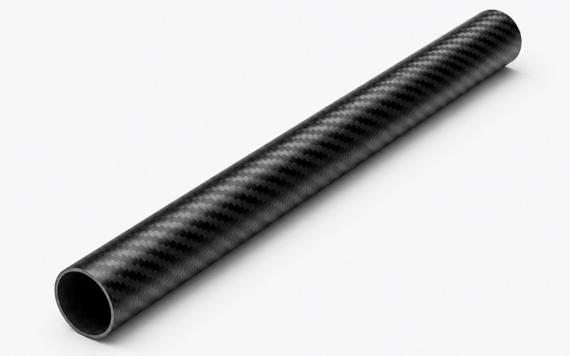
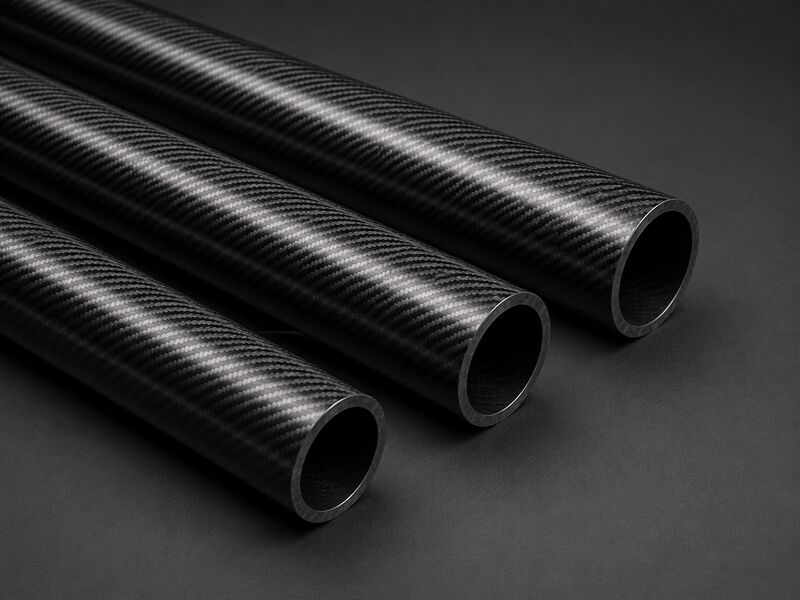
A carbon fiber tube is a composite laminate with carbon fibers locked inside a cured resin matrix. The fibers carry most loads, while the resin transfers shear and stabilizes the shape.
Cutting breaks fibers and resin at the same edge, so tool force must stay controlled. Poor cutting can separate plies, expose fibers, and weaken bonded joints.
Why Abrasive Cutting Works Better
Abrasive cutting grinds through the tube instead of lifting fibers with tooth impact. This reduces ply peeling, especially on thin walls and glossy outer layers.
A diamond wheel keeps a fine contact zone and limits sudden mechanical shock. Heat, dust, and feed pressure still need control during the cut.
How to Cut Carbon Fiber Tube Step by Step?
A clean tube cut comes from layout accuracy, internal support, stable clamping, controlled abrasive cutting, and protected edge finishing.
Measure and Tape the Cut Line
Use a controlled layout process before clamping the carbon fiber tube:
-
- Mark the tube with a wraparound guide so the line meets evenly around the circumference.
- Apply masking tape to protect the surface and create a clearer visual reference.
- Place the tape edge exactly at the cut location.
- Check the alignment again before clamping.
- Confirm the marked line is square to the tube axis before cutting.
Misaligned tape causes taper, uneven insert fit, and poor assembly squareness.
Use an Internal Mandrel or Plug
Insert a close-fitting mandrel, plug, or sacrificial core inside the tube before cutting. Internal support resists ovalization and reduces exit-side splintering.
The support should contact the inner wall without forcing the tube out of round. Excessive plug pressure can preload the laminate and start hidden cracks.
Clamp With a V Block
Hold the tube in a padded V block to prevent rolling during the cut. The block spreads contact pressure and helps maintain square tool entry.
Clamp only firmly enough to stop movement under feed pressure. Overclamping can crush thin walls, print marks into the surface, or distort the kerf.
Cut With a Diamond Wheel
Use a continuous-rim diamond cutoff wheel and let the abrasive surface do the work. Feed slowly to avoid heat buildup and fiber pullout.
Keep the wheel perpendicular to the tube axis unless an angled cut is required. If the tube is large, rotate the tube gradually instead of forcing deep entry.
Do not twist the wheel inside the kerf. Side loading can chip the laminate and widen the cut face.
Deburr and Seal the Edge
Remove loose fibers with fine abrasive paper or a small diamond file. Work from the outside toward the cut face to avoid lifting outer plies.
Apply a compatible epoxy edge seal after cleaning dust from the cut. Sealing limits moisture ingress, loose fiber release, and edge abrasion during service.
Tools for Cutting Carbon Fiber Tube
Tool choice affects chip size, edge heat, dust generation, squareness, and the risk of laminate damage.
Diamond Cutoff Wheel
A diamond cutoff wheel is the common choice for trimming carbon fiber tube. It abrades fibers cleanly and avoids the grabbing action of coarse teeth.
Select a thin, rigid wheel that tracks straight under light pressure. A worn or glazed wheel generates heat and may polish resin instead of cutting efficiently.
Abrasive Chop Saw
An abrasive chop saw works for repeat tube cuts when fitted with a suitable diamond wheel. The saw must have low runout and a secure fixture.
Use controlled descent rather than forcing the head through the laminate. A sudden drop increases exit splintering and can deflect thin tube walls.
Carbide Blade
A carbide blade can cut some carbon fiber tubes, but tooth geometry matters greatly. Fine teeth and stable support reduce impact damage at the entry edge.
Carbide tools dull quickly in abrasive carbon fiber composites. As the edge wears, cutting force rises and delamination risk increases.
CNC Diamond Routing
CNC diamond routing is useful when tubes need slots, fish-mouth cuts, or repeated notches. Fixtures must stop vibration and support the laminate near the tool path.
Program shallow engagement and steady feed to prevent chatter. Poor chip extraction can recut carbon dust and leave rough fiber bundles on the edge.
Waterjet Cutting Limits
Waterjet cutting can trim CFRP parts, but tube geometry creates control issues. Jet exit can wash inner plies and leave a tapered cut.
Water may enter exposed porosity or unsealed interfaces. Secondary drying and sealing are often needed before bonding or assembly.
Carbon Fiber Tube Construction
Tube manufacturing method, fiber path, resin chemistry, wall design, and tow format all influence cutting response.
Pultruded, Roll Wrapped, and Filament Wound Tubes
Different tube constructions respond differently during cutting:
- Pultruded tubes often have strong lengthwise fiber alignment and consistent section shape.
- Pultruded axial fibers can fuzz if the tube is unsupported during cutting.
- Roll wrapped tubes may contain layered prepreg with different ply angles.
- Roll wrapped tubes need careful control to prevent cosmetic outer plies from lifting at the tape line.
- Filament wound tubes can include helical fiber paths that may break out unevenly without steady rotation.
Fiber Direction and Ply Orientation
Fibers parallel to the tube length tend to bridge across the kerf before fracturing. This can leave whiskers if the wheel is dull or pressure is high.
Angle plies cut differently because the wheel crosses fibers diagonally. Mixed orientations require balanced support so no ply group peels away first.
The safest setup keeps the tube stable and the abrasive contact consistent. That control protects stiffness, fatigue life, and bonding reliability near the cut.
Resin Type and Cutting Response
Epoxy, vinyl ester, and other matrices respond differently to heat and abrasion. A tougher resin may resist chipping but smear if the wheel overheats.
Brittle resin systems can crack ahead of the cut under excessive feed pressure. The cutting process should balance wheel sharpness, cooling, and light contact.
Match edge sealing materials to the tube resin when possible. Compatibility improves adhesion and reduces later edge whitening or debonding.
Wall Thickness and Kerf Pressure
Thin tube walls need internal support because the wheel can push the wall inward. This deflection opens plies and creates an angled cut face.
Thicker walls tolerate higher contact load but retain more heat near the kerf. Feed must still stay smooth to prevent resin burn and microcracking.
When wall thickness changes along a part, adjust support and feed through the transition. Ignoring the change can create a visible step at the edge.
Tow Size and Edge Quality
Large tow bundles can leave a more visible fiber pattern at the cut face. Smaller bundles often give a finer edge when the laminate is well consolidated.
Tow size also affects how fibers fracture under abrasion and how visible the fiber bundles appear at the cut face. Poorly wetted bundles may pull out instead of cutting flush.
Inspect exposed bundles after cutting and before sealing. Loose tow ends indicate tool wear, poor support, or a local laminate defect.
Clean Tube Cutting Parameters
Clean cuts require matched wheel geometry, speed, feed, support, rotation method, and dust or coolant strategy.
Wheel Diameter and Kerf Width
Wheel diameter controls reach, stiffness, and exposure at the cut. A larger wheel may clear fixtures, but it can increase vibration if poorly supported.
Kerf width affects material loss and edge heat. A narrow kerf reduces waste, yet it must remain rigid enough to avoid wandering.
Choose the wheel for tube size, wall stiffness, and required squareness. Replace it when tracking becomes unstable or cutting force rises.
Surface Speed and Feed Rate
Surface speed should keep abrasive grains cutting rather than rubbing the resin. Too little speed can grab fibers, while excess speed can overheat the matrix.
Feed rate should be light and continuous. Stop-start feeding leaves witness marks and may create cracks at the cut face.
Operators should watch dust color, edge sound, and wheel behavior during cutting. Darkened dust or a sharp odor suggests heat damage.
Low Force for Thin Walls
Thin carbon fiber tube requires low cutting force and strong internal backing. The goal is to fracture fibers without bending the wall.
Let the abrasive wheel advance gradually through the laminate. If the wall flexes, the kerf can pinch and chip the outer ply.
Use short passes or staged rotation when needed. This reduces local pressure and improves roundness near the finished edge.
Tube Rotation and Indexing
Rotating the tube during cutting reduces deep radial loading from the wheel. It also keeps the abrasive contact more uniform around the circumference.
Indexing is useful when a machine cannot rotate continuously. Each indexed position should overlap the previous cut without leaving uncut fibers.
Check that the reference line remains aligned after each movement. Slippage during indexing creates faceted cuts and assembly gaps.
Dry Cutting vs Wet Cutting
Dry cutting and wet cutting both work, but each method has different controls:
- Dry cutting is simple and avoids liquid contamination before bonding operations.
- Dry cutting requires effective dust extraction at the source.
- Wet cutting can reduce airborne dust and heat.
- Wet cutting creates slurry that must be controlled and cleaned.
- Water trapped in the laminate edge can affect adhesive bonding and sealing.
Choose the method based on dust controls, resin sensitivity, and downstream processing. Always clean and dry the edge before inspection or bonding.
Carbon Fiber Tube Cutting Defects
Most cutting defects come from tool wear, poor support, high force, heat, porosity, or unsupported exit edges.
Delamination
Delamination occurs when plies separate near the cut line. It usually results from high tool force, poor backing, or a dull abrasive wheel.
Control it by taping the line, supporting the inner wall, and using light feed pressure. Keep the wheel sharp and avoid side loading the kerf.
Visible delamination reduces bearing area for bonded inserts and clamps. Hidden delamination can spread under cyclic loading.
Fiber Pullout
Fiber pullout appears as loose strands or ragged bundles on the cut edge. It often indicates insufficient resin support or worn cutting media.
Lower feed pressure and improve internal support before repeating the cut. A finer abrasive action can leave fibers flush with the resin matrix.
Pullout reduces edge quality and complicates sealing. It can also create stress risers where clamps contact the tube.
Resin Burn and Edge Cracks
Resin burn appears as darkened, glossy, or brittle material near the cut. It occurs when friction heat exceeds the resin’s stable machining response.
Reduce heat by using a sharper wheel, lighter feed, or better cooling strategy. Do not keep the wheel stationary in the kerf.
Edge cracks can follow resin burn because the matrix becomes brittle. Cracked edges should be trimmed back or evaluated before use.
Porosity and Dry Spots
Porosity and dry spots may already exist inside the tube before cutting. Machining exposes them as pits, dull areas, or loose fiber clusters.
These defects reduce local interlaminar strength and can trap moisture. Edge sealing helps only after unstable fibers and contamination are removed.
If defects repeat across many cuts, inspect the source tube batch. The issue may relate to consolidation, resin flow, or cure control.
Exit Side Splintering
Exit side splintering happens when the wheel breaks through unsupported laminate. The last fibers bend outward before they are fully abraded.
Use an internal plug and reduce feed near breakthrough. Rotating the tube also spreads the exit load around the circumference.
Splintered exits interfere with insert seating and can cut adhesive films. Rework may shorten the tube and affect final length control.
Tube Edge Finishing and Tolerance
Finishing converts a cut tube into a usable component with controlled length, squareness, bond surface, and sealed fibers.
Length and Squareness Control
Length control starts with a stable stop, clear reference face, and consistent wheel path. Squareness depends on fixture alignment and minimal tube deflection.
Verify the cut face against the design datum before finishing. Sanding cannot correct a severely angled cut without removing excessive material.
For assemblies, squareness affects load sharing between tubes, inserts, and bonded joints. Poor geometry creates gaps and uneven adhesive thickness.
Flat Cut Faces for Inserts
Bonded inserts need a flat tube face and a clean internal wall. Gaps at the face can concentrate load in the adhesive bondline.
After cutting, lightly dress the face on a controlled abrasive surface. Keep pressure even so the tube end remains square.
Remove dust before trial fitting any insert. Carbon dust can prevent adhesive wetting and reduce bond reliability.
Chamfering and Burr Removal
Chamfering removes fragile fibers at the inner and outer rim. A small chamfer reduces handling damage and improves insert entry.
Use fine abrasive tools and avoid prying motions at the edge. Aggressive deburring can lift plies or expose longer fiber strands.
Vacuum the edge during finishing when possible. Loose carbon debris can contaminate nearby bond surfaces.
Epoxy Edge Sealing
Epoxy edge sealing locks exposed fibers and closes capillary paths at the cut face. The sealant should wet the edge without forming thick runs.
Clean the cut face before applying the seal. Dust, oil, or coolant residue can cause poor adhesion.
Allow the seal to cure before clamping or bonding near the end. Premature loading can crack the seal and expose fibers again.
Visual and Ultrasonic Inspection
Inspection should confirm both visible edge quality and hidden laminate condition:
- Visual inspection checks splintering, resin burn, fiber pullout, and edge continuity.
- Angled light helps reveal raised plies and cracks.
- Ultrasonic inspection can detect subsurface delamination near critical tube ends.
- Inspection results should be linked to cutting records and tool condition.
- Cutting feedback helps prevent repeat defects in production.
Safety and Dust Control
Carbon fiber tube cutting produces fine conductive dust, sharp fibers, and airborne particles that require controlled extraction and protection.
Carbon Fiber Dust Protection
Carbon fiber dust can irritate skin, eyes, and breathing passages. Use protection and cleanup methods that control fine conductive particles:
- Wear suitable respiratory protection during cutting.
- Use gloves, sleeves, and eye protection.
- Do not blow dust with compressed air.
- Clean the area with vacuum extraction and damp wiping when appropriate.
- Keep contaminated wipes away from electrical cabinets and clean bonding areas.
Air jets spread fibers across equipment, clothing, and nearby work surfaces.
Conductive Dust Control
Carbon fiber dust is electrically conductive, so it can bridge terminals and harm electronics. Keep cutting away from open drives, controls, and test equipment.
Use grounded extraction equipment and avoid dust accumulation on benches. Conductive debris can also create measurement errors during electrical testing.
Plan cable routing and tool placement before cutting begins. Good housekeeping reduces both safety risk and rework risk.
HEPA Vacuum Extraction
HEPA vacuum extraction captures fine carbon fiber particles close to the cut. Position the nozzle near the wheel without disturbing the fixture.
Use filters and hoses suitable for conductive composite dust. Standard shop vacuums may leak fine particles or create electrical hazards.
Inspect extraction performance during long cutting jobs. Reduced airflow allows dust to settle on bond surfaces and machine guides.
End Use Requirements
The cut end must support the tube’s final load path, bonding method, clamping system, and inspection requirement.
Load Path Alignment
Carbon fiber tube strength depends on how loads enter the laminate. A cut that is not square can shift load into local bending.
Insert faces, brackets, and clamps should contact the tube evenly. Uneven contact creates stress concentration and may start edge cracks.
Align the cut with the intended fiber load path whenever possible. This protects axial stiffness, torsional response, and fatigue behavior.
Surface Prep for Bonding and Clamping
Prepare the tube end based on the final joining method:
- Clean carbon dust from the cut face and internal wall.
- Abrade bonding areas when required by the adhesive process.
- Seal exposed fibers where specified.
- Remove loose fibers before clamping.
- Document the cut, finish, and cleaning method for critical assemblies.
Carbon dust and glossy resin reduce wetting and bond strength. A clamp over damaged laminate can crush plies and reduce tube durability.
FAQ
Can Carbon Fiber Tube be Cut With a Hacksaw?
Yes, but it is usually rougher than abrasive cutting. Use fine teeth, tape, support, and slow pressure.
What Blade is Best for Cutting Carbon Fiber Tube?
A continuous-rim diamond cutoff wheel is usually preferred. It grinds fibers with less tooth impact and cleaner edges.
How Do You Stop Carbon Fiber Tube From Splintering?
Tape the cut line and support the tube internally. Use light feed pressure and a sharp diamond wheel.
Should Carbon Fiber Tube be Wet Cut or Dry Cut?
Either method can work when properly controlled. Dry cutting needs extraction, while wet cutting needs careful drying.
How Do You Seal a Carbon Fiber Tube After Cutting?
Clean the edge and remove loose fibers first. Apply compatible epoxy so it wets the exposed laminate evenly.