Carbon Fiber Sheet Cutting Basics
Proper carbon fiber cutting requires abrasion control, dust capture, heat management, and support for the laminate edge.
CFRP Sheet Structure
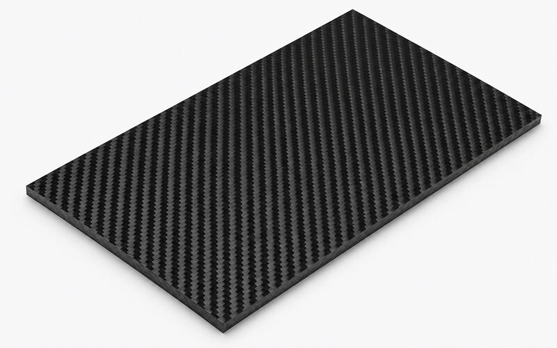
A carbon fiber sheet is a cured laminate made from fiber reinforcement and polymer resin. Cutting passes through fibers, matrix, and ply interfaces at the same time.
The fibers carry most tensile load, while the resin transfers shear between plies. Poor cutting can break fibers, lift plies, or expose unsealed edges.
Thickness, Weave, and Resin Effects
Thickness, weave, and resin behavior all affect cutting response:
- Thicker sheet needs more rigid support because tool pressure can flex the laminate.
- Plain weave usually resists local yarn movement better than open fabrics.
- Twill fabric can show attractive surfaces but may fray along diagonal tow paths.
- Epoxy resin softens when cutting heat rises, which can smear resin and reduce edge definition.
Flexing changes kerf shape and increases breakout on the exit side. Sharp abrasive tools help control heat and protect the laminate edge.
How to Cut Carbon Fiber Sheet Step by Step?
A controlled sequence reduces chipping, delamination, dust release, and dimensional drift during manual or CNC cutting.
Set Tolerance and Kerf Width
Set tolerance and kerf width before cutting production parts:
- Set machining tolerance at 0.2 mm when the part requires close fit.
- Verify tool runout before cutting to reduce rework on mating CFRP components.
- Measure a sample cut because kerf width depends on blade thickness, abrasive wear, and tool deflection.
- Compensate the cut path for the measured kerf, not the catalog tool width.
Carbon fiber abrasive wear can widen the cut during longer operations.
Mask and Mark the Cut Line
Apply masking tape over the cut zone before marking the carbon fiber sheet. The tape supports surface fibers and makes the scribed line easier to see.
Use a fine marker or knife scribe without cutting deeply into the laminate. Deep scoring can start a crack along the outer ply.
Mark the waste side clearly and keep the line away from loaded edges. This prevents accidental removal of structural material.
Use a Backing Board
Clamp the sheet to a flat backing board during cutting. The board supports the exit side and reduces breakout when fibers leave the tool path.
Use sacrificial material that will not melt or load the abrasive wheel. Replace it when grooves stop supporting the laminate.
Full contact matters because gaps allow vibration under the tool. Vibration promotes edge chipping and loose fiber bundles.
Cut With Low Heat and Vibration
Use light pressure and a steady feed so the abrasive edge cuts rather than burns. Excess pressure creates heat, tool wander, and resin smear.
Keep the workpiece clamped near the cut line without crushing the laminate. Firm support limits chatter and protects the surface weave.
Pause if the edge darkens, smells strongly, or shows glossy melted resin. Those signs indicate thermal damage near the cut.
Inspect and Finish the Edge
Inspect the cut edge before removing masking tape. Look for lifted plies, loose tow ends, white stress marks, and resin burn.
Dress minor roughness with fine abrasive paper on a hard block. Sand along the edge, not aggressively across the outer ply.
Seal exposed edges when moisture, wear, or electrical contact matters. Sealing also stabilizes loose fiber ends after machining.
Tools for Cutting Carbon Fiber Sheet
Tool choice depends on sheet thickness, required accuracy, edge quality, and available dust control.
Hacksaw and Coping Saw
A hacksaw can cut thin carbon fiber sheet when only simple trimming is needed. Use a fine abrasive or carbide grit blade, not a coarse wood blade.
Keep the sheet clamped between sacrificial boards to reduce chatter. Slow strokes lower heat and prevent sudden fiber pullout.
A coping saw helps with small internal shapes after a starter hole. It is slower but gives good control on prototype parts.
Rotary Tool and Diamond Wheel
A rotary tool with a diamond wheel is useful for trimming, notching, and short straight cuts. Diamond abrasive cuts the fibers without relying on tooth geometry.
Use shallow passes and let the wheel clear dust continuously. A loaded wheel heats the resin and creates ragged edges.
Hold the tool square to the sheet and avoid side loading. Side pressure can snap the wheel and gouge the laminate.
Jigsaw With Carbide Blade
A jigsaw can cut carbon fiber sheet when the panel is well supported. Use a carbide grit blade and disable aggressive orbital action.
Support both sides of the line because the reciprocating motion lifts plies. Masking and a backing board reduce top-side chipping.
Do not force tight curves with a wide blade. Blade twisting increases delamination and leaves an uneven kerf.
Angle Grinder
An angle grinder cuts rapidly with a diamond wheel, but it creates high dust and heat. It suits rough trimming more than precision fitting.
Use light contact and keep the wheel moving through the cut. Lingering in one spot burns resin and darkens the edge.
Because grinders are difficult to guide, leave stock for final sanding. This protects the final line from tool wander.
CNC Router and Waterjet
CNC routing and waterjet cutting suit different sheet cutting needs:
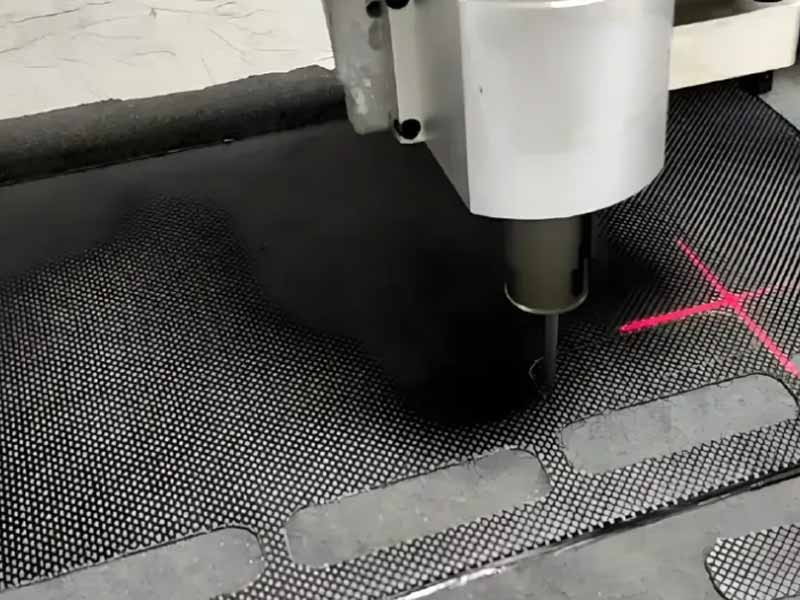
- CNC router cutting gives repeatable profiles when fixturing, dust extraction, and tool selection are correct.
- Diamond coated tools resist abrasion better than steel cutters during CNC routing.
- Waterjet cutting avoids tool wear and cuts complex shapes without mechanical vibration.
- Waterjet cutting may affect porous or poorly sealed laminates if water enters the edge.
Choose CNC routing for dry, controlled edges and fast nesting. Choose waterjet when heat input and tool forces must stay low.
Safety When Cutting Carbon Fiber Sheet
Cutting CFRP releases conductive, respirable dust that must be controlled at the tool and workstation.
Protective Equipment
Use protective equipment that matches fine composite dust and sharp laminate edges:
- Wear respiratory protection suitable for fine composite dust during cutting and sanding.
- Use safety glasses or a face shield to protect against wheel fragments and fiber splinters.
- Use gloves when handling cut edges because broken fibers are sharp.
- Avoid loose gloves near rotating tools.
- Protect exposed skin when cutting large panels for long periods.
Carbon fiber dust can irritate skin and clothing seams.
Carbon Fiber Dust Hazards
Carbon fiber dust is abrasive, conductive, and difficult to clean from equipment. It can irritate lungs and may create electrical faults inside unprotected electronics.
Fine dust also contaminates bonding surfaces and paint areas. Keep cutting operations separated from layup, bonding, and inspection stations.
Dry sweeping spreads particles back into the air. Use extraction, wet wiping, or approved vacuum systems instead.
Dust Extraction and Wet Cutting
Local extraction should collect dust close to the cutting point. A shroud around the tool improves capture and reduces airborne fibers.
Wet cutting suppresses dust and lowers heat at the edge. It requires drying and inspection before bonding or sealing.
Do not let contaminated slurry enter general drains without proper handling. Carbon fiber residue can settle and remain conductive.
CNC Cutting Carbon Fiber Sheet
CNC cutting improves repeatability when tool wear, feed control, support, and coolant strategy are managed together.
Diamond Coated Router Bits
Diamond coated router bits resist the severe abrasion caused by carbon fibers. Standard carbide tools dull quickly and then push fibers instead of cutting them.
Use compression-style geometry when both faces need cleaner edges. Upcut tools clear dust well but can lift the top ply.
Inspect the cutting edge regularly under magnification. Worn coating increases heat, fuzzing, and dimensional drift.
Spindle Speed and Feed Rate
Spindle speed and feed rate must create cutting, not rubbing. Rubbing polishes the resin, heats the edge, and accelerates tool wear.
Increase feed carefully when dust becomes powdery and the edge remains cool. Reduce feed when the part vibrates or fibers tear.
Use test coupons from the same laminate before cutting valuable panels. Different resin systems and ply schedules respond differently to the same program.
Vacuum Table and Spoilboard
A vacuum table holds flat sheets without clamps crossing the tool path. Uniform support prevents local lift and protects thin features.
The spoilboard must be flat, clean, and porous enough for vacuum flow. Dust buildup reduces holding force and allows micro movement.
Small parts need tabs, skins, or auxiliary retention during final pass. Loose parts can catch the cutter and chip finished edges.
Climb Milling and Edge Quality
Climb milling often improves edge quality because the tool enters the surface with controlled engagement. It can reduce fiber lifting on the visible face.
The machine must be rigid because climb cutting can pull the tool into the work. Backlash or weak fixturing causes chatter and oversize edges.
Test conventional and climb directions on the actual weave orientation. Some laminates show different tearout along warp and weft directions.
Waterjet Cutting Control
Waterjet cutting uses a high-energy abrasive stream instead of a rotating tool. This reduces mechanical load and avoids router bit wear.
Control pierce strategy because the initial jet can chip the entry surface. Start in scrap zones or use lead-ins where possible.
Dry the sheet fully after cutting and inspect for edge moisture. Water retained in defects can weaken later adhesive bonding.
Carbon Fiber Sheet Cutting Quality
Edge quality depends on fabric architecture, fiber grade, resin behavior, and laminate stacking sequence.
Weave Type and Tearout
Weave type affects how fibers are supported as the cutting tool exits the laminate. Tight weaves resist yarn movement better than open decorative fabrics.
When a blade pulls unsupported yarns, tearout appears as fuzzy edge bundles. Masking, sharp abrasives, and backing support reduce this defect.
Cut direction also matters because woven tows change angle across the panel. Test cuts should include both main fabric directions.
Fiber Type and Abrasion
High modulus carbon fiber is stiff and can be more brittle at the machined edge. It may chip more easily under vibration.
Standard modulus fiber usually tolerates handling better during trimming. However, all carbon fibers abrade cutting tools rapidly.
Select tools for abrasion resistance before optimizing speed. A sharp, stable cutting edge prevents heat and fiber pushout.
Tow Size and Edge Fray
Use a 3K tow when the part needs a fine surface weave and stable laminate appearance. The smaller bundle helps reduce visible edge fray after cutting.
A 12K tow improves production handling but exposes larger bundles at machined edges. Larger bundles can leave more noticeable fuzz if support is poor.
Match tow size to cosmetic, structural, and machining requirements. Edge finishing effort often increases as exposed bundle size rises.
Resin Heat Sensitivity
Resin heat sensitivity controls how much heat the cutting process can tolerate. Excess heat softens, smears, or discolors the matrix near the edge.
Thermoset epoxy usually chars rather than remelts after full cure. Still, friction can create local damage before the operator notices.
Use sharp abrasive tools, steady feed, and dust clearing to reduce heat. Burn marks often indicate weakened resin and poor bond preparation.
Ply Schedule and Delamination
Ply schedule affects how cracks move from the cut edge into the laminate. Balanced stacking reduces directional distortion during machining.
Unidirectional outer plies can split along the fiber direction when unsupported. Woven outer plies often give better edge containment.
Place critical fibers away from aggressive trimmed edges when design allows. This improves damage tolerance around holes, slots, and exposed profiles.
Cutting Holes and Slots
Internal features need controlled entry, support, and tool selection to prevent breakout and stress concentration.
Pilot Holes and Starter Holes
Use pilot holes before enlarging holes or starting internal saw cuts. They guide the tool and reduce wandering on the hard laminate surface.
Back up the exit side before drilling through the sheet. Unsupported exits can splinter fibers and lift the final ply.
For routed slots, use a programmed lead-in where geometry allows. This keeps entry damage outside the finished profile.
Carbide Drills and Hole Saws
Carbide drills and abrasive hole saws handle CFRP better than standard twist drills. Their edges resist wear and maintain cleaner hole geometry.
Use brad-point, dagger, or composite drill forms when available. These geometries reduce grabbing and exit breakout.
Clear dust during drilling to prevent heat buildup inside the hole. Packed dust increases friction and can polish the wall.
Slot Width and Edge Distance
Slot width must match fastener, insert, or cable clearance without removing unnecessary laminate. Narrow slots concentrate stress if corners remain sharp.
Keep edge distance based on the load path and fastener type. Too little material beside a slot encourages splitting under service load.
Use rounded slot ends rather than sharp internal corners. Rounded ends reduce crack initiation from machined defects.
Exit Side Breakout Control
Exit side breakout occurs when the tool pushes fibers away from the last supported ply. This is common during drilling and plunge cutting.
Use a backing board, reduced thrust, and sharp tools to support the exit face. Inspect both faces because the entry side may look acceptable.
If breakout appears, change the drill geometry or cut from both sides. Do not rely on sanding to remove deep ply lifting.
Edge Finishing and Defect Control
Finishing removes minor machining defects and prepares the edge for service, sealing, bonding, or assembly.
Delamination and Fiber Pullout
Delamination appears as separated plies or white lines near the cut edge. Fiber pullout appears as loose strands extending from the laminate.
Both defects reduce edge durability and can create crack starters. They also interfere with accurate fitting and adhesive bonding.
Control them with backing support, sharp abrasive tools, and stable feed. Severe delamination usually requires recutting beyond the damaged zone.
Heat Damage and Burn Marks
Heat damage shows as dark resin, glossy smear, or a sharp burnt odor. It is caused by rubbing, dull tools, or insufficient dust clearing.
Burned resin can lose strength and may bond poorly after finishing. The damage may extend below the visible surface.
Reduce tool contact time and use lighter passes when heat appears. Replace worn wheels or bits instead of increasing pressure.
Sanding and Edge Radius
Sanding should remove burrs without cutting deeply into load-bearing fibers. Use a hard block to keep the edge straight.
A small edge radius reduces handling splinters and lowers local stress concentration. It also helps coatings or sealers cover exposed fibers.
Move progressively to finer abrasives only after defects are removed. Polishing over torn fibers hides damage without correcting it.
Tolerance Inspection
Inspect tolerance after the part cools and dust is removed:
- Remove dust from corners, holes, slots, and outside profiles before measuring.
- Use consistent datum points from the engineering drawing or fixture.
- Support flexible thin sheets in the same condition each time.
- Record deviations by feature type, such as holes, slots, and outside profiles.
- Review deviation patterns to identify tool wear, fixture movement, or wrong kerf compensation.
Inspection After Cutting
Post-cut inspection confirms that machining did not compromise strength, bonding, sealing, or assembly accuracy.
Visual Edge Inspection
Visual inspection should cover both faces and the exposed edge. Look for fray, delamination, thermal marks, chips, and inconsistent kerf width.
Use bright angled light to reveal lifted fibers and resin whitening. Magnification helps separate cosmetic texture from real ply damage.
Document defects before sanding if process improvement is required. Finishing can remove evidence of the original cutting problem.
Strength and Fatigue Effects
Cutting defects can reduce static strength when they interrupt load-carrying fibers. They can also shorten fatigue life by creating crack initiation sites.
Holes and slots are especially sensitive because stresses concentrate around internal features. Edge quality matters more when loads cycle repeatedly.
For critical CFRP components, validate cutting procedures with representative test coupons. Testing links machining damage to actual design allowables.
Bonding, Fastening, and Sealing
Bonded edges must be clean, dry, and free of loose fibers. Cutting dust reduces wetting and creates weak adhesive interfaces.
Fastened joints need clean holes with controlled breakout. Damaged hole walls can reduce bearing strength and clamp stability.
Seal exposed edges when moisture, galvanic contact, or handling wear is expected. Sealing also reduces fiber release during service.
FAQ
Can You Cut Carbon Fiber Sheet With a Jigsaw?
Yes, a jigsaw can cut carbon fiber sheet with a carbide grit blade. Clamp the sheet firmly and support the exit side.
What Blade is Best for Cutting Carbon Fiber Sheet?
Diamond abrasive or carbide grit blades are preferred for carbon fiber sheet. They resist fiber abrasion better than standard toothed blades.
How Do You Cut Carbon Fiber Sheet Without Fraying?
Use masking tape, backing support, sharp abrasive tools, and light feed pressure. Finish the edge gently and seal loose fibers if needed.
Should Carbon Fiber Sheet be Cut Wet or Dry?
Wet cutting controls dust and heat but requires drying before bonding. Dry cutting needs strong extraction at the cutting point.
Can Carbon Fiber Sheet be Laser Cut?
Laser cutting is generally unsuitable for structural CFRP sheet. The resin can char and leave a heat-affected edge.