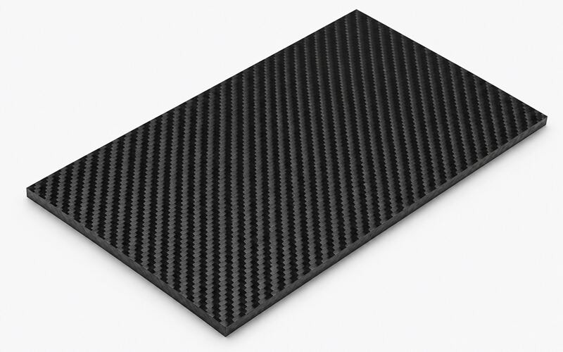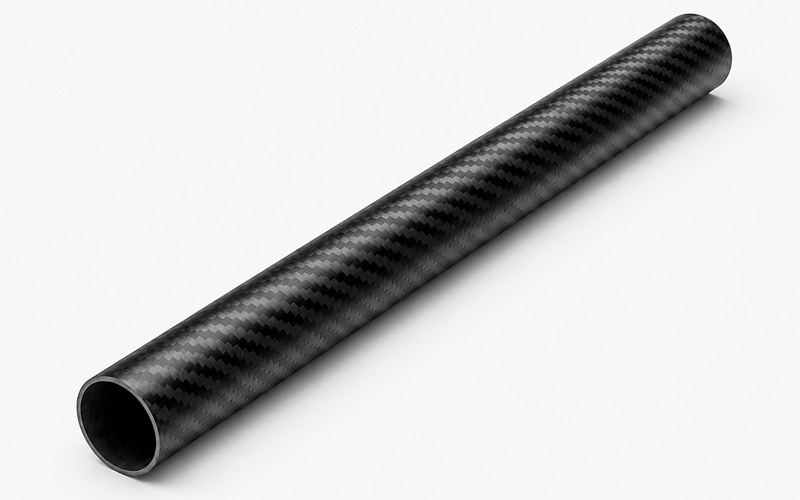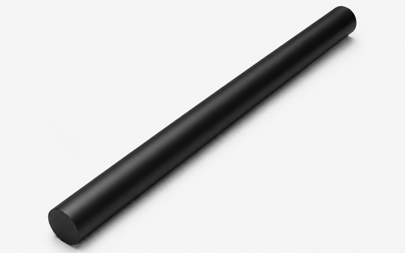
For material-specific instructions, see our guides to cutting carbon fiber sheets, cutting carbon fiber tubes, and cutting carbon fiber rods. This overview explains how to choose a cutting method and control dust, heat, and edge damage.
How to Cut Carbon Fiber Cleanly?
Clean carbon fiber cutting depends on tool choice, laminate support, dust control, and controlled heat generation.
Cutting Sheets, Tubes, Rods, and Fabric
Different carbon fiber forms need different cutting control:
- Carbon fiber sheets need firm backing because unsupported laminate edges can chip during tool exit.
- Tubes need secure cradles or V-blocks to limit vibration and distortion; some cutting setups also use controlled rotation. Solid rods generally require firm, distributed support rather than rotational support.
- Fabric and prepreg need shear cutting, drag knives, or ultrasonic knives to prevent tow distortion.
- Masking may help protect cosmetic surfaces, while appropriate sharp tooling, stable support, and controlled feed are more important for limiting chipping and breakout.
Thickness, Fiber Direction, and Resin Effects
Thicker laminates often require adjusted feeds, speeds, tooling, and pass depths to manage cutting forces and heat; simply reducing feed is not always the best solution. Excess heat can soften epoxy, smear the edge, and weaken local interlaminar bonding.
Fiber direction changes cutting resistance because tools meet continuous carbon filaments at different angles. Cutting across dominant fibers can cause splintering when clamping is weak.
Brittle resin systems chip more easily than tougher matrices. Control feed pressure and tool sharpness to keep cracks from spreading into the laminate.
Carbon Fiber Cutting Tools
Tool selection depends on part form, required accuracy, edge finish, dust control, and available workholding.
Hacksaw and Coping Saw
A hacksaw can cut carbon fiber tube, rod, or small sheet when production volume is low. A suitable fine-tooth, carbide-grit, or abrasive blade may work, depending on laminate thickness and the saw. Coarse blades can snag fibers and damage edges.
Clamp the part close to the cut to reduce vibration and fiber lifting. Use light, controlled strokes and inspect the cut periodically. Excess force or poorly supported material can cause angled cuts, fraying, or delamination.
Rotary Tool and Dremel
A rotary tool cuts small openings, trim lines, and light contour work in cured CFRP components. Use reinforced abrasive wheels or diamond wheels to abrade fibers instead of tearing them.
Avoid prolonged contact in one location, which can overheat or degrade the resin. Monitor wheel wear and avoid forcing the tool. Vacuum extraction near the cut is important because rotary tools release fine conductive dust.
Angle Grinder
An angle grinder may be used for rough trimming by trained operators, but it provides limited dimensional control and can produce substantial airborne dust. Use only a wheel rated for the tool and confirmed suitable for composite cutting; a general-purpose metal cutoff disc is not automatically appropriate.
The tool must be guided carefully because lateral pressure can delaminate unsupported edges. Use light passes, stable clamping, and dust capture to limit heat and airborne particles.
Jigsaw
A jigsaw can cut carbon fiber sheet, but blade selection and support are critical. A composite-compatible fine-tooth or abrasive blade, firm backing, and a controlled cutting action can reduce chipping. Down-cut blades may protect the top face but can affect the opposite face, so test the complete setup.
High vibration can start matrix cracks around tight curves. Use modest feed, a sacrificial support panel, and relief cuts when changing direction.
Wet Tile Saw
A suitably configured wet saw with a composite-compatible diamond blade may be useful for straight cuts in some cured carbon fiber laminates. Confirm that the saw manufacturer permits the material and that the laminate can tolerate wet cutting.
Water can suppress airborne dust, but contaminated slurry requires collection and appropriate disposal. Some laminates, especially cored or previously damaged parts, may be sensitive to moisture; assess material compatibility, dry as needed, and protect electrical equipment.
Precision Carbon Fiber Cutting
Precision cutting needs controlled motion, suitable abrasive tooling, stable fixturing, and inspection of the finished edge.
CNC Router Cutting
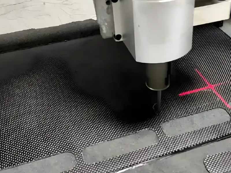
CNC router cutting is common for flat panels, cured laminates, and nested production parts. It controls tool path, feed, and depth more consistently than manual cutting.
Specify dimensional tolerances from the engineering drawing and verify them against the laminate thickness, part geometry, workholding, cutter, and machine capability. A single tolerance value should not be applied to every CFRP part; tighter features may require process trials and inspection.
Vacuum hold-down, tabs, or mechanical fixtures must prevent laminate lift during tool exit. Poor hold-down causes chatter, chipped corners, and dimensional drift.
Diamond and PCD Tools
Diamond-coated and polycrystalline diamond (PCD) tools often offer greater wear resistance than uncoated carbide in abrasive CFRP machining. Actual tool life and edge quality depend on tool geometry, laminate construction, cutting parameters, and machine rigidity.
Tool geometry should support shearing without wedging the laminate apart. Dull tools raise cutting forces, heat the resin, and leave fuzzy edges.
Use tooling designed for composites to control wear, cutting forces, and edge damage. Dedicated tooling also helps avoid unwanted cross-contamination where cleanliness is important. Inspect cutting edges before critical parts because small chips can mark every repeated cut.
Waterjet Cutting
Abrasive waterjet cutting can produce complex profiles without the heat-affected zone associated with thermal cutting. It avoids direct contact with a conventional cutting tool, although nozzles and mixing tubes still wear and abrasive-waterjet processing can cause delamination or surface damage.
Suitable fixturing and support help reduce movement and damage. Jet pressure, piercing strategy, standoff distance, abrasive flow, and traverse speed influence delamination, kerf taper, and surface finish.
Evaluate waterjet suitability for the specific resin system, laminate, and any core or bonded construction. Water can enter cut edges or existing defects; controlled piercing, cleaning, drying, and further inspection may be required before bonding or assembly.
Laser Cutting Limits
Conventional laser cutting of cured CFRP can produce a heat-affected zone because carbon fibers and polymer matrices respond differently to concentrated energy. Resin recession, charring, or local damage may occur if laser parameters are unsuitable.
Excessive thermal damage can reduce edge performance and impair subsequent bonding. Appropriate fume extraction and process qualification are required when laser cutting polymer composites.
Specialized pulsed-laser systems and optimized parameters can also cut some cured CFRP laminates with limited heat damage. For load-bearing parts, select and qualify the cutting process based on acceptable damage, inspection results, and the component requirements.
Workholding and Kerf Control
Workholding and kerf control affect movement, vibration, laminate peel, and final dimensional accuracy.
- Fixtures should support the part near both sides of the intended kerf.
- Kerf allowance must be included in the tool path or layout line.
- Sacrificial boards, vacuum tables, and clamps all change edge behavior.
- The chosen method should avoid crushing thin walls or imprinting cosmetic surfaces.
Ignoring kerf compensation can make external profiles undersized and internal openings oversized, depending on which side of the programmed or marked line the cutter follows.
Carbon Fiber Cutting Quality
Cutting quality depends on reinforcement form, weave stability, tow behavior, laminate stack, and resin response.
Dry Fabric and Prepreg Cutting
Dry carbon fiber fabric is cut before resin infusion, RTM, or hand layup. The main risk is fiber tow displacement, which changes local stiffness and appearance.
Use sharp shears, drag knives, or ultrasonic cutters to preserve fabric geometry. Apply light restraint so the fabric stays flat without stretching the weave.
Prepreg cutting adds tack, backing film, and temperature sensitivity to the process. Keep release film controlled because wrinkles can transfer into the layup.
Weave Type and Edge Quality
Plain-weave fabric may resist yarn displacement during handling, but fraying depends on weave density, sizing, cutting method, and fabric condition. Twill weave drapes better, but exposed edges may distort if handling is rough.
Unidirectional tapes need extra support because fibers run continuously along one direction. Cutting across those fibers can lift bundles if the blade is dull.
Edge quality affects bonding because loose fibers reduce adhesive contact. Seal, sand, or trim again when fraying changes the designed edge profile.
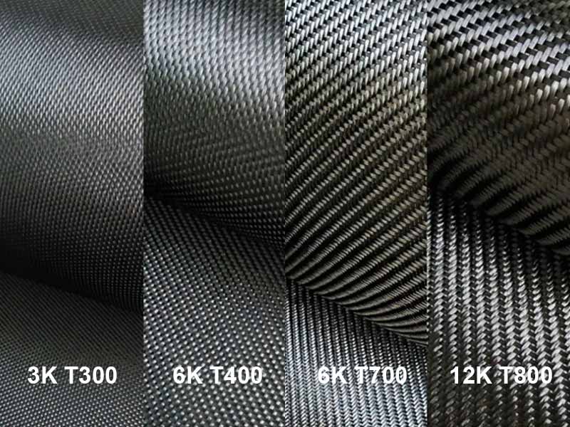
Tow Size and Ply Schedule
Tow size can influence the appearance of a cut edge, but it does not by itself determine cutting speed, fraying, or edge quality. Fabric architecture, resin content, laminate cure, and tooling also matter.
The ply schedule controls how fibers exit the edge through the laminate thickness. Different ply orientations change the local fiber-cutting angle and can produce different patterns of fiber pullout, breakout, and edge damage.
Cut planning should follow the laminate drawing, not only the visible surface weave. Hidden plies can dominate strength around slots, holes, and attachment features.
Resin Heat Sensitivity
Epoxy, vinyl ester, and thermoplastic matrices respond differently to cutting heat. Heat-sensitive resin may soften, smear, or discolor before fibers are fully severed.
Control heat through sharp tooling, lighter passes, coolant, or wet cutting when compatible. Overheated resin can reduce bond quality and hide matrix cracks near the edge.
After cutting, inspect for gloss changes, burnt odor, or smeared dust. These signs indicate that process settings should be reduced or tooling replaced.
Cutting Preparation and Dust Control
Preparation prevents edge defects, protects operators, and reduces rework before machining or manual trimming begins.
Carbon Fiber Dust Safety
Machining CFRP can generate airborne fine particles, including respirable dust, as well as larger fiber fragments. Exposure may irritate skin, eyes, and airways; carbon-rich dust can also create electrical contamination risks in equipment.
- Use suitable local exhaust ventilation and dust extraction with filtration appropriate to the particle size and exposure assessment.
- Wear eye and skin protection. Select respiratory protection according to the exposure assessment, applicable requirements, and the respirator manufacturer’s instructions.
- Keep dust away from motors, control cabinets, and open connectors.
- Clean with vacuum methods rather than compressed air.
Blowing dust spreads conductive particles and contaminates bonding surfaces.
Masking and Cut Line Layout
Masking tape supports surface fibers and makes the cut line easier to see. It also helps reduce cosmetic chipping on visible laminate faces.
Lay out the line from the engineering datum, not from a rough molded edge. Mold flash and trimmed edges can drift from the designed geometry.
Mark both entry and exit faces when accuracy matters. This helps detect blade wander and misalignment before material is removed.
Vacuum and Wet Cutting Control
Vacuum cutting captures dry dust at the source and keeps the work area cleaner. The nozzle should stay close to the kerf without disturbing the tool.
Wet cutting suppresses airborne dust and cools the cut, but it creates contaminated slurry. Collect slurry carefully because carbon particles can conduct electricity after drying.
Choose wet methods only when the laminate, core, and downstream bonding process allow moisture exposure. Dry and seal edges before sensitive assembly steps.
Backing Material for Clean Edges
Backing material supports the underside of carbon fiber sheet during blade exit. This reduces breakout when fibers lose support near the kerf.
Use a compatible sacrificial backing board or fixture, such as suitable MDF or dense plastic where the selected cutting process permits it. The backing should sit flush so vibration cannot hammer the laminate edge.
For curved parts, shaped supports or soft jaws distribute clamping pressure. Poor support can crush thin skins and create hidden delamination.
Cutting Tubes, Rods, and Holes
Round carbon fiber forms need special support because wall pressure, rotation, and drilling forces can split the laminate.
Tube Cut Lines and Fixtures
Tube cutting should follow a controlled sequence:
- Mark the cut line around the full circumference to avoid a spiral edge.
- Use a wraparound guide to align the line on round surfaces.
- Hold the tube square with a V-block, tube cradle, or rotary fixture.
- Rotate the tube gently when using manual abrasive cutting.
- Inspect the wall length and edge quality after cutting.
Unsupported tubes vibrate, which causes splintering and uneven wall length.
Mandrels and Internal Support
A mandrel supports thin tube walls against inward cutting pressure. It is especially useful when the tube has a cosmetic outer surface.
The mandrel should match the internal shape closely without forcing the laminate outward. Excessive fit pressure can create hoop stress before cutting begins.
Internal support also helps drilling and slotting near tube ends. Without support, the tool can break the inner plies as it exits.
Rod Support During Cutting
Carbon fiber rods can split longitudinally if clamped with point pressure. Use soft jaws or grooved supports to spread the load.
Cut near the support, not at a long overhang. Overhang allows bending, blade chatter, and angled ends.
After cutting, inspect the rod end for fiber lifting and other damage. Compatible edge sealing may reduce exposed-fiber damage or moisture uptake where required by the application.
Pilot Holes and Relief Cuts
A pilot hole may help locate some larger holes during manual drilling, but it is not required for every CFRP drilling operation. Composite-specific drill geometries, backing support, and validated cutting parameters are often more important for limiting delamination.
Backing material under the exit side limits breakout during through-holes. Clamp pressure should hold the panel flat without imprinting the surface.
Relief cuts help when trimming internal corners or tight profiles. They prevent the tool from forcing fibers sideways and cracking the matrix.
Slots, Corners, and Fiber Direction
Slots concentrate stress because they interrupt continuous fibers across the laminate. Their ends should be shaped to avoid sharp crack starters.
Cut corners with controlled passes and avoid forcing the tool into the turn. Abrupt direction changes can lift plies along the dominant fiber direction.
When possible, place slots so load paths do not rely on severed fibers. This improves durability around brackets, fasteners, and bonded inserts.
Carbon Fiber Edge Finishing
Edge finishing removes cutting damage, improves handling safety, and prepares CFRP parts for bonding, coating, or assembly.
Deburring and Sanding
Deburring removes loose fibers, resin burrs, and small chips left by cutting. Use fine abrasive paper, diamond files, or abrasive pads with light pressure.
Sand along the edge rather than prying across exposed fibers. Aggressive sanding can undercut resin and leave unsupported filaments.
Keep dust extraction active during finishing because sanding creates fine particles. Clean the edge before inspection, bonding, or sealing.
Chamfering and Edge Radius
Carefully designed chamfers or radii can remove sharp edges and reduce some local stress concentrations, but excessive edge removal can damage plies or alter a dimensionally critical feature.
Use guided abrasive tools or controlled hand sanding for consistent geometry. Uneven chamfers can affect fit where panels meet housings or bonded joints.
Cosmetic parts need careful finishing because exposed fibers reflect light differently. Keep strokes uniform to avoid visible waves along the edge.
Epoxy Edge Sealing
When required, a compatible epoxy or other approved sealant can stabilize exposed edge fibers and cover surface porosity. It is useful after cutting tubes, drilled holes, and trimmed laminate edges.
Apply a thin coat after dust removal and light abrasion. Excess resin can create fit problems or interfere with bonded assemblies.
Properly applied edge sealing may reduce moisture uptake and handling-related fraying, but it does not repair structural delamination or guarantee waterproofing. Follow the sealant manufacturer’s surface-preparation and curing requirements.
Carbon Fiber Cutting Defects
Most cutting defects come from tool wear, poor support, excessive heat, or fiber movement during machining.
Delamination and Fraying
Delamination occurs when cutting forces separate plies instead of severing fibers cleanly. It often appears near tool exit, corners, or unsupported edges.
Fraying comes from loose tow ends and weak resin support at the cut boundary. Masking, backing, and sharper abrasive tools reduce both problems.
If delamination is visible, do not hide it with coating alone. Remove damaged material or rework the edge according to the part specification.
Heat Damage and Tool Wear
Possible signs of overheating include discoloration, resin smearing, unusual odor, or localized surface changes; the appearance varies by resin and surface finish. It results from dull tooling, excessive dwell, or poor chip removal.
Tool wear raises cutting force because carbon fibers abrade cutting edges quickly. Worn tools push fibers aside and create larger damaged zones.
Replace or dress tools when feed pressure increases noticeably. Lower heat improves bond reliability and preserves laminate strength near the cut.
Fiber Pullout and Matrix Cracks
Fiber pullout happens when the tool grabs filaments instead of cutting them. It leaves a fuzzy edge and can reduce local bearing strength around holes.
Matrix cracks form when vibration or wedging stresses exceed resin toughness. These cracks may spread under fatigue or moisture exposure.
Control both defects with rigid fixturing, sharp abrasive tooling, and correct feed pressure. Inspect dark laminate carefully because cracks can hide in the weave.
Inspection and Measurement
Inspect cut carbon fiber parts for chips, fray, discoloration, and delamination before finishing. Visual checks should cover both faces and the exposed edge.
Measure critical profiles after dust removal because loose fibers can affect contact readings. Use the specified tolerance from the drawing for accept or rework decisions.
For structural CFRP components, document visible defects before finishing and apply the relevant inspection or engineering acceptance criteria. Documentation helps link cutting settings to later testing or assembly performance.
FAQ
What is the Best Tool to Cut Carbon Fiber Sheet?
CNC routing with composite tooling and abrasive or diamond-wheel cutting are common options for cured carbon fiber sheet. A suitably configured wet saw may work for certain laminates. Choose based on thickness, required tolerance, edge integrity, dust control, and equipment compatibility.
Can Carbon Fiber Be Cut With a Dremel?
Yes, a Dremel can cut small carbon fiber features. Use reinforced abrasive or diamond wheels and capture dust close to the kerf.
How Do You Cut Carbon Fiber Without Splintering?
Support the laminate, mask the cut line, and use sharp abrasive tooling. Avoid heavy feed pressure because it lifts fibers and starts delamination.
Should Carbon Fiber Be Cut Wet or Dry?
Wet cutting reduces dust and heat, but it creates conductive slurry. Dry cutting needs strong vacuum extraction and careful respiratory protection.
What Blade is Best for Cutting Carbon Fiber?
Diamond, carbide-grit, PCD, and specialized carbide cutters are possible options, depending on the process. Tool geometry, edge sharpness, machine setup, and laminate construction matter more than a universal blade ranking.