Carbon Fiber Manufacturing Overview
Carbon fiber production converts carbon-rich precursor fibers into tow, fabrics, prepregs, and finished CFRP components.
From Raw Material to Carbon Fiber Tow
Carbon fiber starts as a controlled precursor fiber with consistent chemistry and filament shape. The precursor is stabilized, carbonized, surface treated, sized, and wound into tow.
Each stage controls fiber alignment, carbon structure, surface energy, and handling behavior. Poor control can reduce tensile strength, resin bonding, or tow spreading quality.
From Carbon Fiber Tow to Fabric, Prepreg, and CFRP Parts
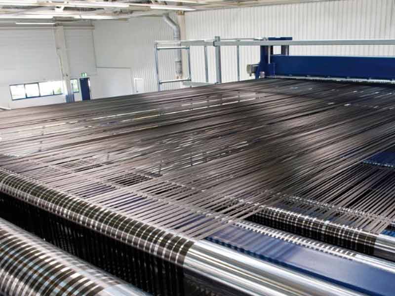
Tow is converted into unidirectional tape, woven fabric, braided forms, or spread tow reinforcement. These reinforcements are combined with resin by prepregging, infusion, RTM, or other molding routes.
Fiber direction carries most structural load, while resin transfers shear and protects the filaments. The final CFRP part depends on fiber grade, laminate design, cure control, and defect management.
Raw Materials Used to Make Carbon Fiber
Different precursor materials create different fiber structures, costs, modulus levels, and processing requirements.
| Precursor Type | Main Advantage | Main Limitation | Typical Use |
|---|---|---|---|
| PAN Based Precursor | High strength and stable processing | Requires controlled stabilization and carbonization | Structural CFRP parts |
| Pitch Based Precursor | High stiffness and thermal conductivity | More sensitive processing and brittle behavior | High modulus and thermal management parts |
| Rayon Based Precursor | Useful for selected specialty applications | Lower conversion yield and limited structural use | Thermal insulation and specialty carbon products |
PAN Based Precursor Fiber
PAN based precursor fiber is the dominant route for structural carbon fiber. It provides a strong balance of strength, process stability, and scalable production.
During manufacturing, molecular orientation must be preserved before heat treatment. Any precursor inconsistency can carry through as weak spots in the final tow.
Pitch Based Precursor Fiber
Pitch based precursor can produce very stiff carbon fiber with high graphitic alignment. It is often selected when stiffness, thermal conductivity, or dimensional stability are primary requirements.
The material is more sensitive to mesophase control and spinning conditions. Processing variation can create brittle filaments or inconsistent modulus.
Rayon Based Precursor Fiber
Rayon based precursor is an older carbon fiber route used in selected specialty applications. It offers different char behavior and can support certain thermal insulation products.
Its conversion yield and structural performance are less attractive for many load-bearing CFRP parts. This limits its use in mainstream composite manufacturing.
Why PAN is the Most Common Precursor?
PAN is common because it converts reliably into high strength carbon fiber. It supports continuous processing through stabilization, carbonization, treatment, and winding.
Producers can control filament diameter, orientation, and tow uniformity with mature process equipment. This makes PAN suitable for aerospace, automotive, marine, sporting, and industrial composite parts.
How PAN Based Carbon Fiber is Made?
PAN based carbon fiber is made through controlled fiber forming, heat treatment, surface preparation, and tow handling.
- Polymer spinning: Forms fine PAN precursor filaments.
- Washing and stretching: Removes impurities and aligns polymer chains.
- Oxidative stabilization: Makes the precursor infusible before high heat treatment.
- Carbonization: Removes non-carbon elements in an inert atmosphere.
- Graphitization: Increases carbon layer ordering for high modulus fiber.
- Surface treatment: Improves bonding between carbon fiber and resin.
- Sizing and winding: Protects filaments and prepares tow for later processing.
Polymer Spinning and Precursor Fiber Forming
PAN polymer is dissolved and spun into fine precursor filaments through controlled spinnerets. The spinning method affects filament roundness, internal voids, and later carbonization behavior.
Coagulation, solvent removal, and draw conditions must remain stable across the tow width. Poor spinning creates defects that cannot be fully removed during heat treatment.
Washing, Stretching, and Fiber Alignment
The precursor is washed to remove solvent and impurities that could disturb later reactions. Stretching aligns polymer chains along the fiber axis.
Better alignment improves load transfer after carbonization and raises usable strength. Overstretching or uneven draw can cause filament breaks, tow fuzz, or inconsistent mechanical properties.
Oxidative Stabilization
Stabilization heats PAN precursor in controlled air so the polymer becomes infusible. This step prevents the fibers from melting during later high heat exposure.
Tension, airflow, residence time, and temperature uniformity affect chemical conversion. Incomplete stabilization can cause filament fusion, mass loss, and reduced carbon fiber strength.
Carbonization in an Inert Atmosphere
Stabilized fibers pass through inert furnaces where non-carbon elements are removed. Nitrogen is commonly used to prevent oxidation during this conversion.
Fiber tension controls shrinkage and helps preserve alignment. Incorrect atmosphere control can oxidize the fiber surface and reduce tow strength.
Graphitization for High Modulus Fiber
Graphitization uses higher heat treatment to increase carbon layer ordering. This process raises stiffness but can reduce strain capability.
Producers select this route when high modulus carbon fiber is required. Furnace control is critical because uneven heating creates inconsistent stiffness along the tow.
Surface Treatment for Resin Bonding
Fresh carbon fiber surfaces are relatively inert after carbonization. Surface treatment introduces functional groups that improve bonding with resin systems.
The treatment level must match the intended matrix and final application. Excess treatment can weaken filaments, while insufficient treatment can cause delamination.
Sizing and Tow Winding
Sizing applies a thin protective coating to improve handling and resin compatibility. It reduces fuzz, filament breakage, and abrasion during weaving or prepregging.
The sizing chemistry must match epoxy, vinyl ester, or thermoplastic processing needs. Tow winding must maintain stable tension to avoid spreading defects and twisted packages.
How Carbon Fiber Tow is Classified?
Tow classification helps engineers select reinforcement form, surface appearance, mechanical behavior, and processing efficiency.
1K, 3K, 12K, and 24K Tow Size
Tow size describes the filament count within each carbon fiber bundle. Use 3K tow when the part needs fine weave appearance and controlled drape.
Larger tow improves deposition speed and can reduce handling cost in thicker laminates. Tow choice affects fabric texture, resin wet-out, laminate thickness, and surface finish.
Standard Modulus and High Modulus Carbon Fiber
Standard modulus fiber is often selected for balanced strength, stiffness, and processability. High modulus fiber is used when deflection control matters more than impact tolerance.
The selected modulus changes laminate design because stiffer plies carry load differently. Designers must consider brittleness, drilling response, and joint stress concentration.
High Strength Carbon Fiber Grades
High strength grades are chosen when tensile load capacity and damage tolerance are critical. The fiber grade must be matched with resin toughness and layup orientation.
Strong fiber alone cannot compensate for voids, waviness, or poor cure. Testing should confirm that the laminate achieves the intended design allowables.
How Carbon Fiber Fabric is Made?
Carbon fiber fabric production organizes tow into reinforcement forms with specific drape, stability, appearance, and load paths.
Unidirectional Carbon Fiber Tape
Unidirectional tape places most fibers in one load direction. It is used when stiffness and strength must be placed efficiently.
Tape alignment must be controlled during handling, cutting, and layup. Misalignment reduces axial performance and can create local laminate distortion.
Plain Weave Carbon Fiber Fabric
Plain weave interlaces tow in a simple over-under pattern. It offers good stability during cutting and manual placement.
The frequent crimp reduces straight fiber efficiency compared with unidirectional reinforcement. It is useful for flat panels, cosmetic surfaces, and parts needing balanced handling.
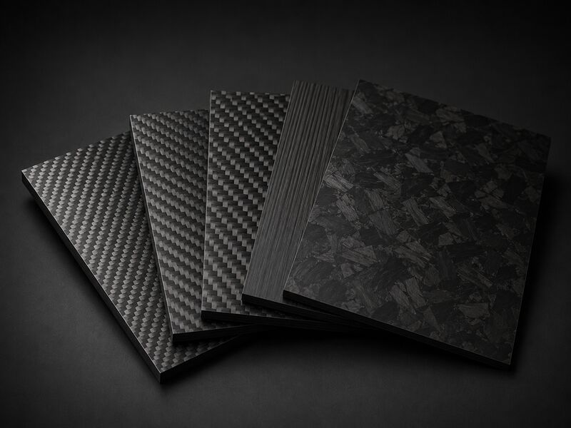
Twill Weave Carbon Fiber Fabric
Twill weave has a diagonal pattern and better drape than plain weave. It conforms more easily over curved molds and complex surfaces.
Lower crimp can improve surface appearance and fiber efficiency. However, the fabric can distort if handled without controlled tension.
Satin Weave Carbon Fiber Fabric
Satin weave reduces tow interlacing and improves drape over compound curves. It can help create smoother visible surfaces in molded carbon fiber parts.
The fabric is more prone to shifting during cutting and layup. Operators must control orientation to avoid uneven local stiffness.
Spread Tow Carbon Fiber Fabric
Spread tow fabric opens each bundle into a wider, flatter band. This reduces crimp and can create thinner, more uniform laminates.
Better filament distribution supports improved resin wet-out and surface smoothness. The material requires careful handling because spread bands can split or distort.
How Carbon Fiber Prepreg is Made?
Prepreg combines carbon fiber reinforcement with controlled resin content, tack, flow, and cure behavior.
Resin Impregnation Process
Prepregging forces or films resin into carbon fiber tape or fabric. The process controls wet-out while preserving fiber alignment and fabric architecture.
Resin viscosity, line speed, pressure, and temperature affect impregnation quality. Poor impregnation creates dry zones, void pathways, or uneven laminate thickness.
Epoxy, Vinyl Ester, and Thermoplastic Resin Systems
Epoxy is common in structural prepreg because it supports controlled cure and strong adhesion. Vinyl ester can suit corrosion-resistant parts and lower-temperature processing routes.
Thermoplastic resin systems provide weldability and improved toughness in selected designs. Resin selection affects storage, forming temperature, cure cycle, and long-term durability.
Prepreg Resin Content and Tack Control
Resin content controls laminate weight, fiber volume, surface finish, and void sensitivity. Too much resin creates resin-rich areas and unnecessary mass.
Too little resin can prevent complete wet-out and reduce interlaminar strength. Tack must be controlled so plies stay positioned without trapping air.
Cold Storage and Shelf Life Requirements
Many prepregs require cold storage to slow resin advancement before use. Warm exposure reduces tack life and can change flow during cure.
Materials should be tracked by batch, out-time, and storage history. Expired prepreg can cure unevenly or produce brittle laminate regions.
How Carbon Fiber Composite Parts are Made?
CFRP parts are formed by arranging reinforcement, adding resin, consolidating the laminate, and curing the matrix.
- Dry fabric layup: Places dry reinforcement into the mold before resin addition.
- Prepreg layup: Uses resin-controlled plies for stable laminate quality.
- Autoclave curing: Applies heat, vacuum, and external pressure for high-performance laminates.
- Resin infusion and RTM: Use controlled resin flow through dry reinforcement.
- Compression molding: Forms repeatable parts in matched metal tooling.
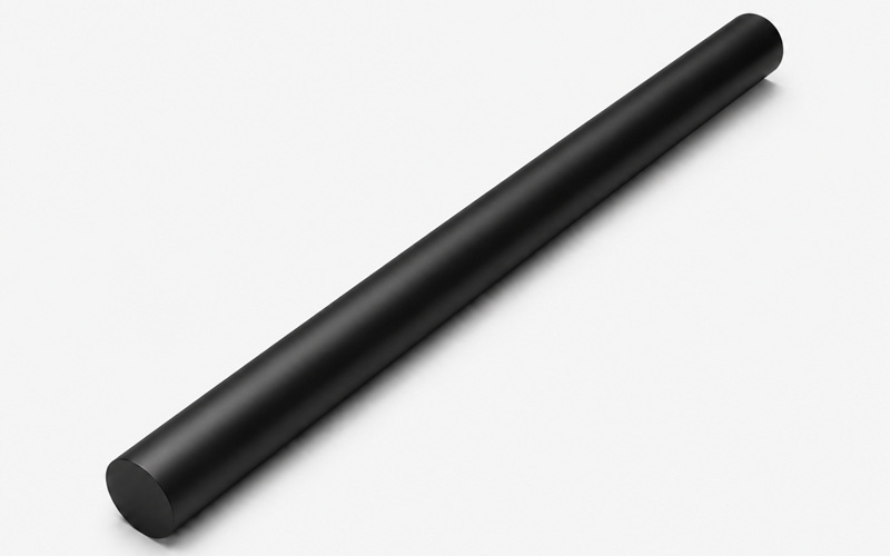
- Pultrusion: Produces constant-section rods, beams, and strips.
- Filament winding: Builds tubes, shafts, and cylindrical structures with controlled winding angles.
Common Defects in Carbon Fiber Manufacturing
Defects usually come from poor wet-out, trapped air, fiber movement, cure imbalance, or weak interfaces.
| Defect | Main Cause | Effect on CFRP Parts | Control Method |
|---|---|---|---|
| Porosity and Voids | Trapped air, moisture, or volatiles | Lower interlaminar strength and fatigue resistance | Dry materials, correct vacuum, and stable cure timing |
| Dry Spots | Poor resin wet-out | Weak local load transfer | Controlled resin flow, compaction, and viscosity |
| Resin Rich Areas | Excess resin pooling | Added weight and local stiffness variation | Balanced compaction and controlled resin distribution |
| Fiber Waviness | Poor drape, excess compaction, or unstable tow tension | Reduced axial strength and stiffness | Accurate cutting, ply placement, and debulking |
| Delamination | Contamination, poor bonding, impact, or inadequate cure | Lower shear transfer and damage tolerance | Clean handling, compatible sizing, and verified cure conditions |
Porosity and Voids
Porosity forms when air, moisture, or volatiles remain inside the laminate. Voids reduce interlaminar strength and can accelerate fatigue damage.
Control requires dry materials, correct vacuum, suitable resin flow, and stable cure timing. Inspection is important because small internal voids may not appear on the surface.
Dry Spots and Resin Rich Areas
Dry spots occur when resin does not fully wet the carbon fiber reinforcement. Resin-rich areas occur when resin pools without enough fiber support.
Both defects disrupt load transfer and create local stiffness variation. Flow media, ply compaction, and resin viscosity must be controlled during molding.
Fiber Waviness and Misalignment
Fiber waviness reduces the ability of carbon fiber to carry axial load. It often results from poor drape, excess compaction, or uncontrolled tow tension.
Misalignment also changes laminate stiffness and can increase buckling sensitivity. Accurate cutting, ply placement, and debulking help preserve the designed fiber path.
Delamination and Weak Bonding
Delamination is separation between plies or between fiber and resin. It can result from contamination, poor surface treatment, impact, or inadequate cure.
Weak bonding reduces shear transfer and damage tolerance. Clean handling, compatible sizing, and verified cure conditions reduce this risk.
Carbon Fiber Machining After Curing
Cured carbon fiber parts often need trimming, drilling, routing, sanding, inspection, and edge sealing.
CNC Cutting and Routing
CNC cutting defines final part edges after molding and curing. Tool geometry, feed strategy, and fixturing affect delamination and dimensional accuracy.
Carbon fiber is abrasive, so dull tools raise heat and fray fibers. Stable vacuum fixtures reduce vibration and help protect thin laminate edges.
Drilling and Edge Finishing
Drilling carbon fiber requires sharp tools and supported exit surfaces. Poor drilling can cause breakout, splintering, or interply separation around holes.
Edge finishing removes loose fibers and prepares surfaces for assembly or sealing. Hole quality matters because fasteners concentrate load around drilled regions.
Dust Extraction and Tool Wear Control
Carbon fiber dust is conductive and abrasive, so extraction is required during machining. Dust control protects equipment, operators, and electronic systems near the work area.
Tool wear should be monitored because worn cutters increase heat and edge damage. Consistent tool replacement improves repeatability and reduces scrap.
Edge Delamination and Sealing
Edge delamination can start during trimming, drilling, or rough handling. Open edges may absorb moisture or expose weak ply interfaces.
Sealing protects the laminate and improves durability in service. Inspection after sealing confirms that loose fibers and cracks were removed.
FAQ
What Raw Material is Used to Make Carbon Fiber?
Most structural carbon fiber is made from PAN precursor fiber. Pitch and rayon are used for selected specialty fibers.
Why is PAN Used to Make Most Carbon Fiber?
PAN gives reliable strength, stable processing, and scalable tow production. It also supports consistent fiber alignment through heat treatment.
What Temperature is Used to Make Carbon Fiber?
Production uses heated air stabilization, inert carbonization, and higher graphitization for selected grades. The exact temperature depends on precursor chemistry and target modulus.
What is the Difference Between Carbon Fiber Fabric and Prepreg?
Carbon fiber fabric is dry reinforcement without a controlled resin system. Prepreg already contains resin, tack, and a defined cure response.
How are Carbon Fiber Sheets and Tubes Made?
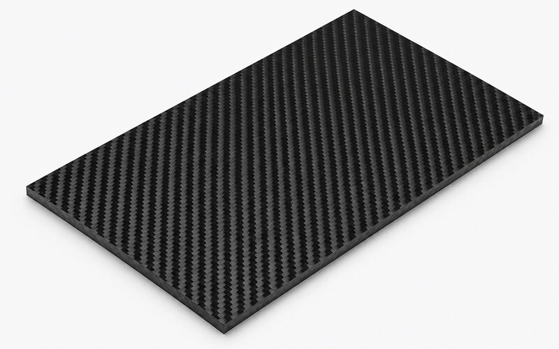
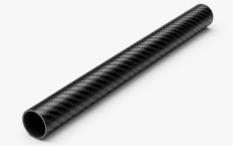
Carbon fiber sheets are made by laying up fabric or prepreg and curing flat laminates. Tubes are made by wrapping, rolling, pultrusion, or filament winding.
What Defects Should be Checked After Carbon Fiber Molding?
Check for voids, dry spots, resin-rich areas, wrinkles, delamination, and dimensional drift. Internal inspection may be needed when defects are not visible.