Carbon fiber and carbon composite describe related but distinct materials within reinforced structures.
Carbon fiber refers to the thin filament that supplies tensile strength within a composite structure.
Carbon composite describes the combined system of reinforcement fiber and cured resin. The resin binds fibers, transfers load, and defines the finished part geometry.
Key Differences
Four factors separate raw fiber from finished composite structures used in production parts.
Carbon fiber is raw tow, fabric, or tape before it becomes a finished structural material.
| Factor | Carbon Fiber | Carbon Composite |
|---|---|---|
| Material Form | Carbon composite is the finished material system made from fiber and cured resin. | |
| Fiber and Resin Functions | Fiber governs tensile strength and stiffness along its alignment direction. | Resin transfers shear stress between fibers, controls surface quality, and improves impact tolerance. |
| Structural Use | Raw carbon fiber cannot bear compressive or shear loads alone without a matrix. | Once impregnated and cured, the composite laminate can carry multidirectional stress. |
| Fiber Length | Carbon fiber may be continuous tow, woven fabric, unidirectional tape, or chopped strands. | Carbon composites may use continuous fiber laminates, chopped fiber compounds, or carbon-filled plastics. |
Material Structure
Internal fiber arrangement determines how a carbon composite distributes and resists applied loads.
| Structure Type | Description | Typical Use |
|---|---|---|
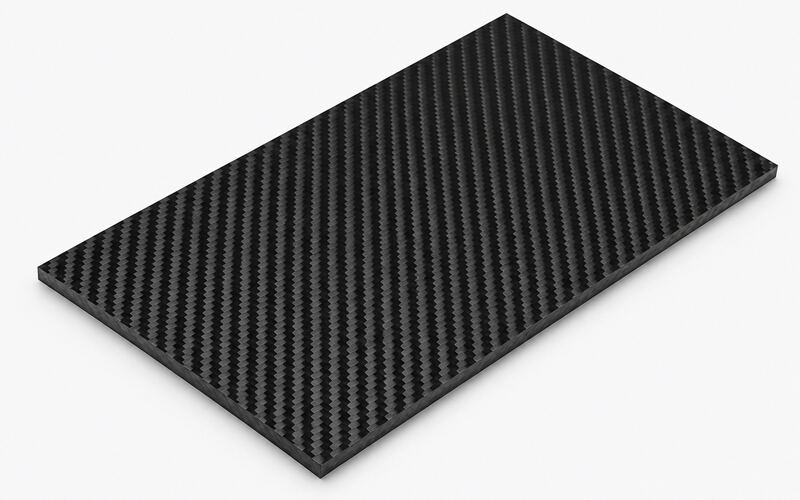
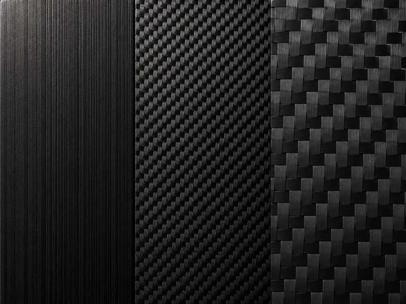
| Woven Carbon Fiber | Woven fabric interlaces tow in perpendicular directions, producing balanced strength along two axes. A 2×2 twill weave offers drapability and a visible surface pattern. | Curved panels, cosmetic surfaces, covers, and moderate structural laminates. |
| Unidirectional Carbon Fiber | Unidirectional fiber aligns all filaments in a single direction, maximizing stiffness and strength along that axis. | Beams, tubes, spars, panels, and parts with clear load paths. |
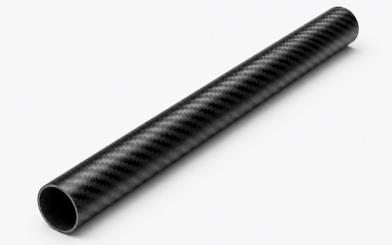
| Continuous Fiber Laminates | Stacked prepreg or dry fabric layers form the strongest carbon fiber structures. Layer count, orientation, and resin content determine thickness and stiffness. | Load-bearing panels, tubes, aerospace parts, motorsport parts, and high-performance structures. |
| Chopped Fiber Composites | Short strands are distributed through injection or compression molding. Random orientation improves molding flexibility but lowers peak strength. | Housings, brackets, covers, and molded parts with moderate strength needs. |
| Carbon-Filled Plastics | Chopped fiber or carbon powder is blended into a thermoplastic base for stiffness and wear resistance. | Non-structural parts, light-duty brackets, electronics housings, and wear-resistant plastic components. |
Resin and Fiber Content
Resin content typically ranges near 35 percent by weight in structural laminates, balancing weight against toughness. Higher resin content adds weight and reduces stiffness, while excessive fiber content raises void risk during curing.
Mechanical Performance
Fiber form and orientation directly shape strength, stiffness, and long-term structural reliability.
Strength-to-Weight Ratio
Continuous fiber laminates deliver the highest strength-to-weight ratio among carbon composite structures.
Chopped fiber composites trail behind because random orientation limits load transfer efficiency along any single axis.
Stiffness Under Load
Stiffness depends on fiber modulus, orientation, and resin content within the laminate.
A higher modulus carbon fiber grade raises stiffness but often reduces impact tolerance and increases brittleness.
Fiber Direction and Load Transfer
Fiber orientation changes stiffness along the primary load direction and governs anisotropic behavior.
Impact and Fracture Behavior
Continuous fiber laminates resist impact through fiber bridging, which slows crack propagation across layers.
Chopped fiber composites fracture more predictably but absorb less energy before failure.
Fatigue and Flex Life
Continuous fiber structures tolerate repeated flexing better than chopped fiber composites because aligned fibers distribute cyclic stress evenly. Resin-rich areas or voids accelerate fatigue crack initiation under repeated loading.
Dimensional Stability
Carbon fiber laminates maintain tight dimensional tolerance because fiber constrains thermal expansion along its axis. Chopped fiber composites shift more under temperature change due to matrix-dominated expansion behavior.
Durability
Surface condition and internal integrity determine how long a carbon composite performs in service.
Surface Wear and Scratching
Woven carbon fiber surfaces resist scratching better than resin-rich chopped fiber parts.
Exposed fiber tow can fray if abrasion penetrates the resin layer.
Impact Damage and Delamination
Sharp impacts can separate laminate layers, causing delamination that weakens compressive strength internally.
Chopped fiber composites resist delamination since no distinct layers exist within the molded structure.
Moisture and Chemical Resistance
Resin selection controls moisture uptake and chemical resistance more than fiber type. Epoxy resin systems resist most solvents, while some thermoplastic matrices swell under prolonged chemical exposure.
Heat and UV Exposure
Extended UV exposure degrades resin before it affects carbon fiber itself, causing surface chalking and discoloration. Elevated temperature near the resin glass transition point softens the matrix and lowers stiffness.
Edge and Surface Damage
Unprotected laminate edges allow moisture ingress and fiber exposure after impact or machining. Sealed edges and coated surfaces extend service life for exterior carbon fiber components.
Manufacturing Methods
Production process selection depends on part geometry, required strength, and target production volume.
| Method | How It Works | Best Fit |
|---|---|---|
| Prepreg Layup and Curing | Pre-impregnated fabric sheets are stacked before autoclave curing under controlled heat and pressure. Curing near 120 °C activates resin crosslinking and helps control void content. | High-performance continuous fiber laminates that need strong mechanical properties and consistent quality. |
| Compression Molding | Chopped fiber sheet molding compound is pressed between heated dies under high pressure. | Medium-volume structural parts that do not require aerospace-grade continuous laminate performance. |
| Resin Transfer Molding | Liquid resin is injected into a closed mold containing a dry fiber preform. Controlled injection pressure reduces void formation. | Parts needing smooth mold-side surfaces and better repeatability than open layup. |
| Injection Molding | Carbon-filled thermoplastic pellets are injected into complex geometries at high production speed. | High-volume molded components where stiffness and wear resistance matter more than peak structural strength. |
| Fiber Orientation Control | Flow patterns, gate placement, layup direction, and cure pressure affect how fibers align and consolidate. | Designs where localized strength, dimensional stability, or defect prevention is important. |
Appearance and Inspection
Visual characteristics offer clues about fiber form but cannot confirm internal structural quality alone.
Visible Weave Patterns
Woven fabric produces a visible crosshatch pattern beneath clear resin coatings. This pattern signals continuous fiber reinforcement rather than chopped fiber content.
Molded Surface Finishes
Chopped fiber composites and carbon-filled plastics show a speckled, non-directional surface texture. This finish indicates random fiber distribution rather than aligned reinforcement.
Edge and Cross-Section Inspection
Cutting a cross-section reveals layer count, fiber alignment, and resin distribution within a laminate.
This inspection method confirms structural composition more reliably than surface appearance alone.
Limits of Visual Identification
Surface appearance cannot confirm fiber volume fraction, void content, or internal fiber orientation. Mechanical testing or cross-section analysis remains necessary for verified performance data.
Cost Differences
Material form, tooling complexity, and labor input jointly determine finished part cost.
Raw Material Cost
Continuous fiber prepreg costs more per kilogram than chopped fiber compound or filled pellets.
Higher fiber grade and tighter quality control raise raw material pricing further.
Tooling and Equipment
Autoclave curing and precision molds raise tooling investment for continuous fiber laminates.
Injection molding tools cost less initially but wear faster under abrasive carbon-filled feedstock.
Labor and Cycle Time
Hand layup of prepreg requires skilled labor and longer cycle time per part. Injection molding and compression molding reduce labor input through automated, repeatable cycles.
Production Volume
Low-volume, high-performance parts favor prepreg layup despite higher unit cost. High-volume production favors injection molding or compression molding for lower per-part expense.
Total Part Cost
Total cost reflects material grade, tooling amortization, labor hours, and inspection requirements combined. Continuous fiber laminates cost more overall but deliver superior strength-to-weight performance for critical structures.
Choosing the Right Material
Selection depends on required strength, part geometry, expected loading, and budget constraints.
When to Use Continuous Fiber Laminates
Choose continuous fiber laminates for structural panels, tubes, or components under sustained directional load. Aerospace and motorsport applications rely on this configuration for verified strength margins.
When to Use Chopped Fiber Composites
Choose chopped fiber composites for brackets, housings, or panels needing moderate strength with complex geometry. Compression or injection molding reduces production cost for these parts significantly.
When Carbon-Filled Plastic Is Enough
Carbon-filled plastic suits components needing stiffness and wear resistance without primary structural load. Consumer electronics housings and light-duty brackets commonly use this material class.
Balancing Weight, Strength, and Cost
Use a structured selection process when comparing carbon fiber, carbon composites, and carbon-filled plastics:
- Define whether the part is load-bearing, cosmetic, protective, or light-duty.
- Check whether the load direction requires continuous fiber reinforcement.
- Review part geometry, molding complexity, and expected production volume.
- Compare the value of weight savings against tooling, labor, and inspection cost.
- Select continuous fiber laminates for critical structures, chopped fiber composites for molded moderate-strength parts, and carbon-filled plastics for non-structural stiffness or wear resistance.
FAQ
Is Carbon Composite the Same as Carbon Fiber?
Carbon fiber is the reinforcement, while carbon composite includes fiber bonded within cured resin. The two terms describe different stages of the same material system.
Is Carbon Fiber Stronger Than Carbon Composite?
Raw carbon fiber has high tensile strength but cannot bear load without resin support. A finished carbon composite converts that fiber strength into usable structural performance.
Which Material Is Stiffer?
Continuous fiber laminates are stiffer than chopped fiber composites or carbon-filled plastics. Fiber alignment and higher fiber volume fraction drive this stiffness advantage.
Is Chopped Carbon Fiber Weaker?
Chopped carbon fiber composites are weaker than continuous fiber laminates along any single direction. Random fiber orientation limits peak tensile and flexural strength.
Does Visible Weave Improve Performance?
Visible weave indicates continuous fiber reinforcement but does not guarantee superior performance alone. Fiber volume fraction, resin quality, and curing control matter more than surface appearance.
Which Material Is More Durable?
Continuous fiber laminates resist fatigue and impact better than chopped fiber composites over repeated loading. Chopped fiber composites resist delamination since no distinct laminate layers exist.
Why Do Carbon Fiber Laminates Cost More?
Prepreg material, autoclave curing, and skilled hand layup raise production cost significantly. These processes deliver higher strength-to-weight ratios that justify the added expense.