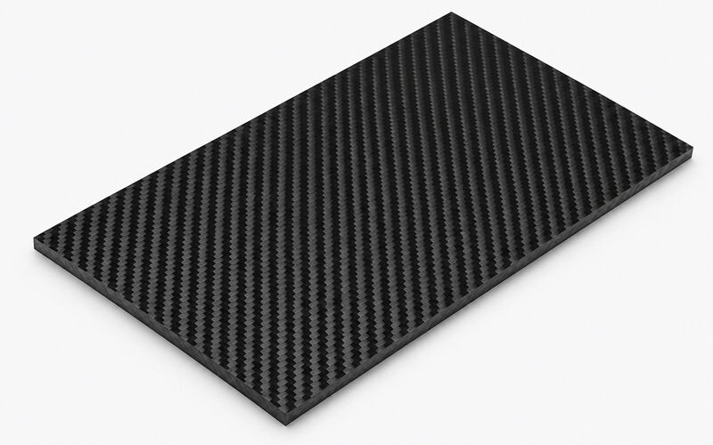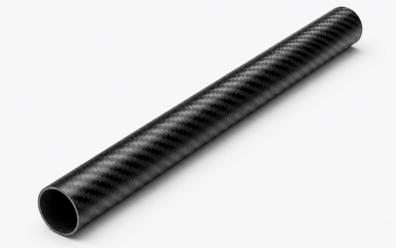
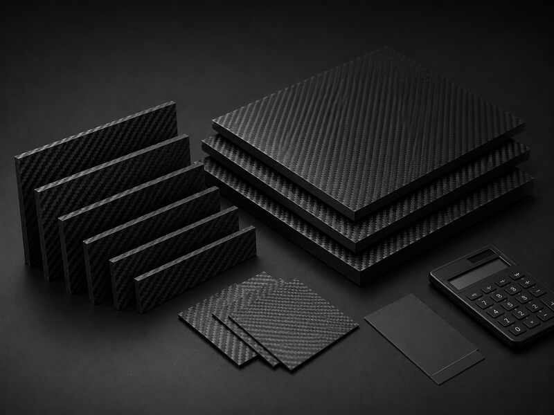
Carbon fiber is a fine carbon-rich filament used as reinforcement. A carbon fiber composite combines those filaments with resin.
The fiber carries most tensile load, while the resin transfers stress between fibers. Without proper resin support, fibers can buckle, abrade, or separate under service loads.
Engineers usually specify a CFRP component, not loose fiber alone. The final performance depends on fiber grade, resin chemistry, layup, cure, and quality control.
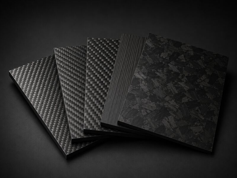
Main Forms of Carbon Fiber
Carbon fiber is supplied in several forms. Each form affects handling, fiber alignment, resin flow, and final part design.
- Tow: Continuous fiber bundles used for weaving, winding, or prepreg production.
- Woven fabric: Fabric with balanced handling and visible surface texture.
- Unidirectional tape: Fibers aligned in one direction for efficient load transfer.
- Prepreg: Carbon fiber pre-impregnated with controlled resin content.
- Chopped fiber: Short reinforcement used in molded parts with complex shapes.
Carbon Fiber Structure and Grades
Carbon fiber grade depends on precursor type, heat treatment, crystal alignment, tow size, and target stiffness.
PAN Based Carbon Fiber
PAN based carbon fiber is common in structural CFRP parts. It offers a balanced combination of tensile strength, stiffness, processability, and availability.
The precursor chemistry allows controlled stabilization before carbonization. Good stabilization limits fiber damage and helps maintain consistent filament quality.
This fiber type is used in aerospace structures, automotive panels, sporting goods, and industrial laminates. Engineers select it when strength, fatigue resistance, and predictable supply matter.
Pitch Based Carbon Fiber
Pitch based carbon fiber is selected when very high stiffness or thermal conductivity is required. Its graphitic structure can align strongly along the fiber axis.
That alignment improves axial stiffness, but it can reduce handling tolerance. Brittle filaments need careful weaving, prepregging, and laminate consolidation.
It is often used in space structures, thermal management panels, and precision equipment. Designers must control transverse loads because the fiber is highly directional.
Carbon Atom Alignment and Fiber Structure
Carbon fiber strength comes from ordered carbon layers aligned along the filament. Better alignment improves axial stiffness and load transfer.
Processing controls this alignment through tension, stabilization, carbonization, and optional graphitization. Poor control can create weak filaments, uneven diameter, or surface defects.
The fiber is strong along its length but weaker across its diameter. Laminate design must align fibers with primary loads to use this structure effectively.
Resin cannot replace lost fiber alignment. It only supports fibers and distributes stress between plies.
Tow Size from 1K to 24K
Tow size describes the filament count inside a carbon fiber bundle. Smaller tow handles fine curves and visible weave patterns more easily.
Larger tow improves deposition speed and can reduce material handling cost. It may also create heavier fabric texture and thicker local buildup.
The chosen tow size affects drape, nesting, resin wet-out, and cosmetic consistency. Poor tow selection can cause fiber waviness or dry zones in tight geometry.
Engineers match tow size to part scale, surface needs, layup method, and required compaction.
Standard Modulus, Intermediate Modulus, and High Modulus Grades
Carbon fiber grades are often selected by stiffness, strength, processing difficulty, and part function.
- Standard modulus: Common for general structural parts with balanced cost and processing behavior.
- Intermediate modulus: Used when higher stiffness is needed without excessive handling difficulty.
- High modulus: Selected for rigidity-critical parts, but it needs careful processing and impact control.
Grade selection must consider load direction, impact exposure, fatigue, and joining method. A stiffer fiber does not always create a tougher laminate.
How Carbon Fiber is Made?
Carbon fiber manufacturing converts precursor filaments into carbon-rich reinforcement through controlled heat, tension, surface treatment, and winding.
Precursor Spinning and Stabilization
Manufacturing starts by spinning precursor polymer into continuous filaments. Filament diameter, tension, and cleanliness affect later fiber consistency.
During stabilization, the precursor is heated in air under controlled tension. This step changes the molecular structure and prevents melting during carbonization.
Uneven stabilization can create weak spots, fuzz, or filament breaks. Process control improves tow uniformity and reduces downstream defects.
The stabilized tow must remain aligned and uncontaminated. Surface contamination can later reduce resin bonding.
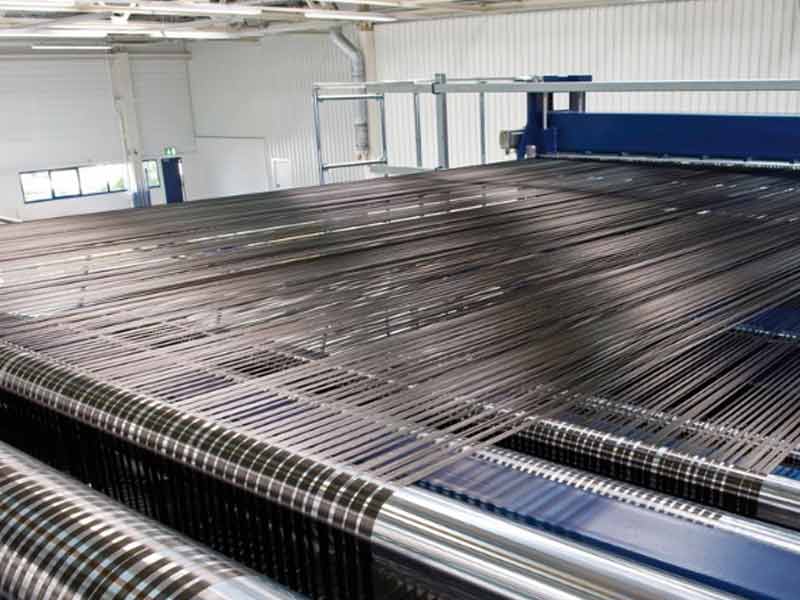
Carbonization in an Inert Atmosphere
Carbonization heats stabilized tow without oxygen. This removes non-carbon elements and forms the carbon-rich fiber structure.
The inert atmosphere prevents burning and protects filament continuity. Tension control keeps filaments aligned during shrinkage.
If gas flow, heat profile, or tension drift, the tow can lose uniformity. Defects may appear as weak filaments or inconsistent electrical behavior.
Carbonization quality affects strength, modulus, surface condition, and batch repeatability. It is a critical step for structural fiber reliability.
Graphitization for High Modulus Fiber
Graphitization uses higher heat treatment to improve carbon layer alignment. This process increases axial stiffness in high modulus fiber.
The treatment must balance stiffness with handling durability. Excessive brittleness can complicate weaving, slit tape handling, and layup.
Graphitized fibers are useful where deflection control is critical. They are less forgiving when impact or tight forming is expected.
Engineers specify these grades only when stiffness justifies processing care. Laminate design must protect them from unfavorable loading.
Surface Treatment, Sizing, and Spooling
After carbonization or graphitization, carbon fiber needs surface preparation before it can be used reliably in composites.
- Surface treatment: Activates the fiber surface and improves resin bonding.
- Sizing: Applies a thin compatible coating to protect filaments during handling.
- Compatibility check: Confirms the sizing works with epoxy, vinyl ester, or thermoplastic resin.
- Spooling: Maintains stable tension and clean packaging before fabric or prepreg production.
Carbon Fiber Composite Materials
Carbon fiber composites combine reinforcement and matrix materials to create parts with controlled shape, strength, and durability.
Why Carbon Fiber Needs a Resin Matrix?
Carbon fibers are strong in tension but need lateral support. The resin matrix holds fibers in position and transfers load between them.
Matrix selection affects toughness, temperature resistance, moisture behavior, and processing route. A weak matrix can cause cracking or delamination.
The matrix also protects fibers from abrasion and environmental exposure. Poor wet-out leaves voids and dry spots that reduce performance.
A good composite design balances fiber content, resin flow, cure control, and service conditions.
Epoxy Resin for Structural CFRP
Epoxy resin is widely used for structural CFRP because it bonds well to treated carbon fiber. It supports high laminate strength and stable fatigue performance.
Epoxy systems must be mixed, stored, and cured according to supplier data. Incorrect cure can leave low glass transition behavior and weak interlaminar strength.
Prepreg epoxy provides controlled resin distribution before molding. Liquid epoxy can suit infusion when flow paths are properly engineered.
Engineers verify compatibility between sizing and resin before production. Poor compatibility can create weak interfaces and early delamination.
Vinyl Ester and Thermoplastic Resin Options
Vinyl ester resins provide good chemical resistance and practical infusion behavior. They are used where corrosion resistance is more important than maximum structural stiffness.
Thermoplastic matrices offer toughness and potential weldability. They often need higher processing energy and more demanding consolidation control.
Resin choice affects cycle time, storage needs, impact tolerance, and repair method. It also changes inspection criteria and joining strategy.
No resin works for every carbon fiber composite. The service environment and manufacturing method must guide selection.
Prepreg Carbon Fiber and Dry Carbon Fiber Fabric
Prepreg and dry carbon fiber fabric use different resin handling methods. The right choice depends on production control, storage conditions, tooling, and part performance requirements.
| Item | Prepreg Carbon Fiber | Dry Carbon Fiber Fabric |
|---|---|---|
| Resin Content | Pre-applied and controlled | Added during molding |
| Storage | Often needs cold storage | More flexible storage |
| Process Control | Needs controlled cure | Needs resin flow control |
| Void Risk | Lower with proper curing | Higher if wet-out is poor |
| Best For | Consistent structural parts | Infusion and wet layup parts |
Carbon Fiber Fabric and Laminate Design
Fabric architecture and ply stacking determine how a carbon fiber laminate carries load and resists damage.
Common Carbon Fiber Fabric Types
Carbon fiber fabric type affects handling, drape, surface appearance, and load transfer. Engineers usually select the fabric based on part shape, load direction, and surface requirements.
- Plain weave: Stable handling and balanced appearance for flat panels.
- Twill weave: Better drape over curves with a diagonal surface pattern.
- Satin weave: Good conformability, but easier to distort during handling.
- Unidirectional fabric: Most fibers run in one direction for efficient load transfer.
- Multiaxial stitched fabric: Reduces crimp and improves layup speed.
Fiber Direction and Layup Design
Fiber direction controls stiffness, strength, and failure mode. Fibers should follow the main load path whenever possible.
Off-axis plies improve torsion resistance, shear transfer, and damage tolerance. Balanced layups reduce warping and residual stress after cure.
Poor layup symmetry can cause spring-in, twisting, or dimensional drift. Ply drops must be tapered to avoid stress concentrations.
Designers also consider holes, inserts, joints, and edges. These areas often need local reinforcement or revised ply orientation.
Thickness and Reinforcement Areas
Laminate thickness is built by adding plies in selected regions. Extra plies increase stiffness and local load capacity.
Reinforcement areas must transition smoothly into surrounding laminate. Abrupt thickness changes can trigger delamination under bending or impact.
Designers reinforce bolt holes, bonded joints, corners, and bearing zones. These locations concentrate stress and often control failure.
Local buildup also affects resin flow and compaction. Tooling must allow air removal around thicker regions.
How Carbon Fiber Composites are Processed?
Processing methods control fiber placement, resin distribution, consolidation, cure, and final part accuracy.
Hand Layup, Vacuum Bagging, and Autoclave Curing
Hand layup places fabric and resin manually into a mold. Operator skill controls ply position, wet-out, and trapped air removal.
Vacuum bagging improves compaction and removes excess air. Leaks can cause porosity, resin-rich zones, or weak laminate areas.
Autoclave curing adds controlled heat and external pressure. This improves consolidation when prepreg materials and qualified tooling are used.
Cure schedules must match resin requirements and part thickness. Poor cure control can reduce strength and distort finished geometry.
Resin Infusion, RTM, and Compression Molding
These molding methods use different tooling, resin flow, and pressure control strategies.
- Resin infusion: Draws liquid resin through dry reinforcement under vacuum.
- RTM: Places reinforcement inside matched tooling before resin injection.
- Compression molding: Uses heat and pressure to form prepreg or molding compounds.
All methods require air removal and resin flow control. Dry spots, race tracking, and fiber wash can reduce structural quality.
Pultrusion and Filament Winding
Pultrusion pulls continuous fiber through resin and a heated die. It produces constant-section carbon fiber profiles.
Fiber alignment is tightly controlled along the profile direction. This improves axial stiffness but limits shape flexibility.
Filament winding places fibers over a rotating mandrel. Winding angle controls pressure resistance, torsion, and axial strength.
Both methods require stable tension and resin control. Poor control can create gaps, waviness, or weak interlaminar regions.
CNC Cutting, Drilling, Sanding, and Edge Finishing
CNC machining trims cured carbon fiber parts to final geometry. Tool sharpness, feed rate, and support affect edge quality.
Drilling must limit delamination at entry and exit surfaces. Backing materials and suitable cutters reduce breakout damage.
Sanding removes flash and prepares bonding surfaces. Overheating can soften resin and smear the machined edge.
Dust extraction is required because carbon fiber dust is conductive and irritating. Finished edges may need sealing against moisture ingress.
Carbon Fiber Properties
Carbon fiber properties depend on fiber grade, laminate architecture, resin matrix, processing quality, and loading direction.
Strength to Weight Ratio and Stiffness
Carbon fiber composites provide high load capacity with low mass. This comes from strong fibers placed along the load direction.
Stiffness depends on fiber grade and ply orientation. Resin-rich laminates add weight without adding equivalent axial stiffness.
Fiber waviness reduces effective stiffness and can lower compressive performance. Good layup control keeps fibers straight and compacted.
Designers should evaluate laminate properties, not only fiber datasheets. Real parts include holes, joints, edges, and manufacturing variation.
Fatigue Resistance and Impact Behavior
Carbon fiber laminates often resist fatigue well under controlled tensile loading. Damage can still grow through matrix cracks and delamination.
Impact behavior depends on resin toughness, layup, thickness, and support conditions. Some damage remains hidden below the surface.
Inspection methods are important after service impacts. Ultrasonic testing, tap testing, or visual inspection may be used as appropriate.
Toughened resin and balanced layups can improve damage tolerance. Local reinforcement helps protect high-risk zones.
Thermal Expansion, Electrical Conductivity, and Corrosion Resistance
Carbon fiber has low thermal expansion along the fiber direction. This helps precision structures maintain dimensional stability.
The material is electrically conductive, so isolation may be required. Contact with certain metals can create galvanic corrosion in wet environments.
CFRP resists many corrosion mechanisms affecting metals. The resin matrix still needs protection from ultraviolet exposure, chemicals, or heat.
Thermal, electrical, and environmental behavior must be reviewed during design. These properties affect bonding, fastening, coating, and grounding choices.
Carbon Fiber Applications
Carbon fiber applications depend on the balance between weight reduction, stiffness, durability, processing cost, and inspection requirements.
Aerospace, Automotive, and Marine Applications
Aerospace uses carbon fiber for stiff, lightweight structures and control surfaces. Certification requires material traceability, process qualification, and inspection.
Automotive applications include body panels, monocoques, brackets, and reinforcement parts. Process speed and repeatability strongly affect viability.
Marine uses include masts, hull panels, hydrofoils, and interior structures. Designers must address moisture, impact, and galvanic isolation.
Each sector uses different resin systems and manufacturing routes. The part function determines laminate architecture and quality requirements.
Industrial, Robotics, Sports, and Consumer Applications
Industrial machines use carbon fiber for beams, rollers, arms, and inspection frames. Low mass can reduce vibration and actuator demand.
Robotics uses carbon fiber tubes and plates for fast moving structures. Stiffness helps improve positioning stability.
Sports equipment uses tuned layups for stiffness, flex, and impact behavior. Bicycles, rackets, and paddles depend on controlled ply placement.
Consumer parts may emphasize appearance and stiffness. They still need sound processing to avoid cosmetic and structural defects.
When Carbon Fiber is Not the Right Material?
Carbon fiber is not suitable when random impact, high bearing load, or low cost dominates. Metals or glass fiber may perform better.
It also needs careful joining and inspection. Poor design can make a lightweight part expensive and difficult to maintain.
FAQ
Is Carbon Fiber the Same as Carbon Fiber Reinforced Polymer?
No, carbon fiber is the reinforcement. Carbon fiber reinforced polymer is the composite made from fiber and resin.
Why is Carbon Fiber Strong but Lightweight?
Carbon atoms align along fine filaments. A laminate uses those filaments where load transfer is needed.
What is the Difference Between Prepreg and Dry Carbon Fiber Fabric?
Prepreg already contains controlled resin. Dry fabric receives resin during wet layup, infusion, or another molding process.
How Do Engineers Choose a Carbon Fiber Grade?
Engineers compare stiffness, strength, toughness, cost, and processability. The final choice depends on load direction and service conditions.